Dirt bike race sag
Dirt bikes with twelve inches of suspension travel typically set shock race sag at four inches and fork sag at two inches. The 2:1 sag ratio requires fork spring rates that are double the shock spring rate at the wheel.
Dirt bikes run a 2:1 sag ratio to force the chassis to fly flat when deflecting off bumps.
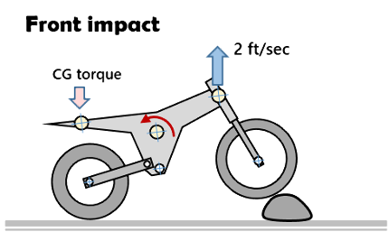
Front wheel impact
- Front chassis deflects off rock impact with a 2 ft/sec vertical velocity
- The front impact transmits a torque through the chassis center of gravity compression the rear suspension
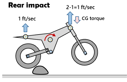
Rear wheel impact
- Rear wheel impacts rock with spring rate set to ½ of fork. The softer rear spring imparts ½ the vertical velocity to the rear chassis, i.e. 1 ft/sec
- Torque transmitted through the chassis center of gravity pinwheels the bike reducing the front vertical velocity by the amount added to the rear
- Front vertical velocity is 1 ft/sec after the rear wheel impact
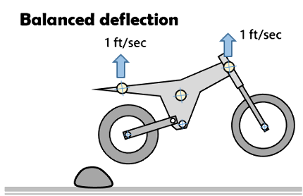
Even deflection
- Bike deflects off rock with equal front/rear vertical velocity
- Front end is higher due to the initial 2 ft/sec vertical velocity
Deflection balance
Dirt bikes set the rear/front sag ratio at 2:1 to force the chassis to fly flat when deflecting off root and rock impacts.
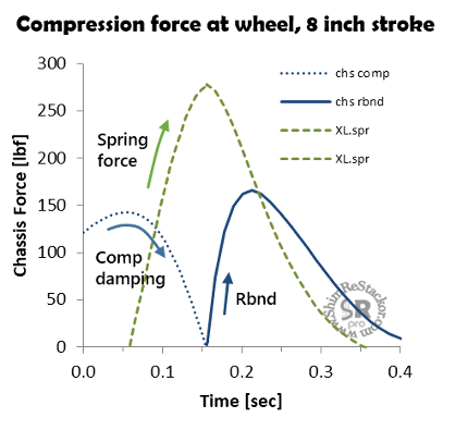
Compression damping fine tunes the front/rear balance. Setting compression damping to the same fraction of the peak spring force preserves the front/rear balance. Gas force, link ratio and fork ICS systems are included in Shim ReStackor calculations of the spring force at the wheel.
Street bike race sag
Street bikes flip the rear/front sag ratio to 0.8:1 running rear spring rates that are stiffer than the front. A street bike with 120 mm of wheel travel typically set fork race sag at 35 and shock sag at 30mm.
The 0.8:1 sag ratio makes the shock spring approximately 20% stiffer than the front following the “flat ride” concept developed by Maurice Olley for Rolls-Royce (1920) and later used by Cadillac (1930). OptimumG outlines the theory.
"Flat ride" theory
- The rear wheel hits a bump after the front
- The time delay between front and rear wheel impact is set by the vehicle speed and wheel base
- To get the rear suspension to return to race sag at the same time as the front, the rear suspension has to move faster than the front. Faster motion requires a stiffer rear spring
The stiffer rear spring used in the “flat ride” concept allows the rear suspension motion to “catch up” to the front so both ends of the chassis return to race sag at the same time. That gives the chassis a flat ride.
The time delay between bump impact on the front and rear wheels is a function of bike speed. Low vehicle speed creates a long time delay requiring the front suspension to move much slower than the rear. Soft front springs needed for the slower response creates a large difference in front/rear race sag, which can be covered up using high preload on the front spring. At 100 mph the time delay is short requiring a smaller 2 mm difference between front and rear race sag.
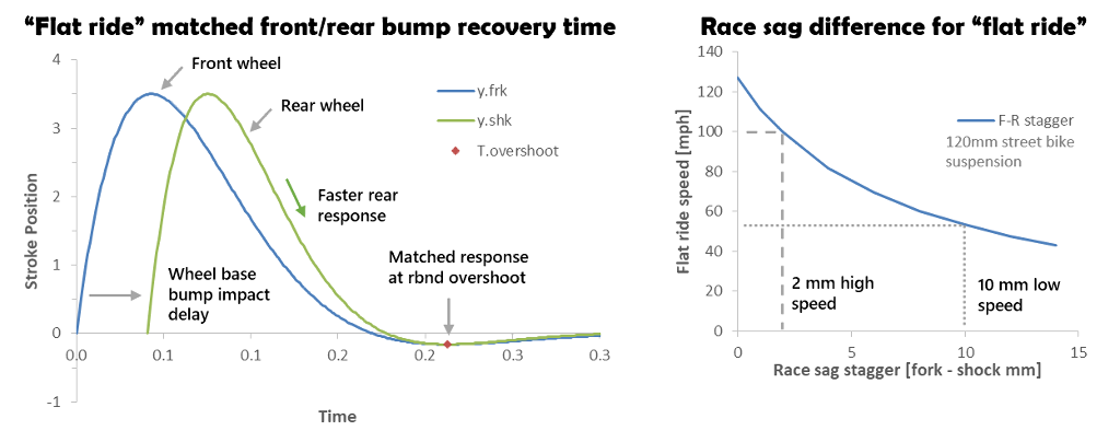
"Flat ride" suspension theory returns rear suspension to race sag at the same time as the front
Supermoto race sag
The 2:1 sag ratio used on dirt bikes is set to force the chassis to fly flat when deflecting off bumps. Using dirt bike sag values for a supermoto setup causes problems in high G corners. The soft rear spring required for a 2:1 sag ratio allows the rear suspension to compress in high G corners. The rear weight transfer unweights the front wheel causing the front wheel to washout mid-corner.
Keeping an even front/rear suspension motion in high G supermoto corners requires spring rates in the 50/50 range or converting over to the street bike “flat ride” concept. Either way, the factor of two change in spring rates needed to repurpose a dirt bike suspension for supermoto requires a complete redo of both compression and rebound damping. ReStackor baseline damping targets provide a starting point for tuning of compression and rebound damping (more).
Chassis race sag
Race sag measures the suspension crush from full extension with the rider weight on the bike. Free sag measures crush with only the bike weight. Motorcycles, trophy trucks and UTV’s all measure sag in terms of chassis sag from full extension.
Shim ReStackor calculations use and report sag in terms of chassis sag.
Motorcycle fork sag is often measured as stanchion tube sag. Stanchion tube sag and chassis sag are different and related by travel ratio:

Response calculation output both chassis and shock shaft sag. For the case below the chassis sag is 2.75” matching the race sag value specified in the inputs. Shock shaft sag is 3.09” measured on the fork stanchion tube.

Response calculation outputs show both chassis sag and stanchion tube race sag
Fork spring rate range
The recommend dirt bike fork stanchion tube sag ranges from 60 to 75 mm with spring preload from 3 to 15 mm and the fork gas pressure bled at race sag or full extension.
The above spec range allows a 180 lbm rider to run spring rates from 0.29 to 0.49 kg/mm.
Selecting spring rate to hit a target race sag is important. However, rule-of-thumb targets for spring preload and race sag allow a wide range of spring rates.
The wide spring rate range emphasizes ride quality is an equally important criterion in selecting spring rate:
- If the suspension rides too stiff, you need a softer spring
- If the suspension bottoms too easily, you need a stiffer spring
Matching race sag specs gets you in the ballpark of spring rate. Final selection is based on rider preference with spring preload adjustments to hit the desired value of race sag.

"Rule of thumb" targets for race sag and spring preload allow a wide range of spring rates
Shim ReStackor race sag calculations
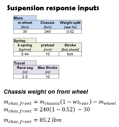
Chassis weight on front wheel
Chassis weight on the front wheel is specified by inputs of wheel weight, bike curb weight and weight split defined by the equation below.
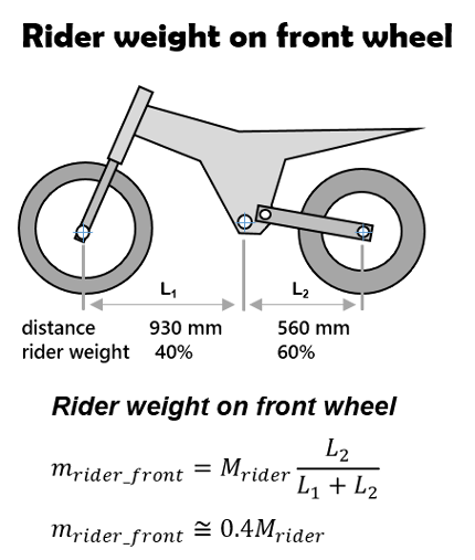
Rider weight on front wheel
Rider weight on the front wheel is determined by the distance from the foot peg to the front and rear axial. Shim ReStackor uses 40% front and 60% rear for all bikes.
Rider weight
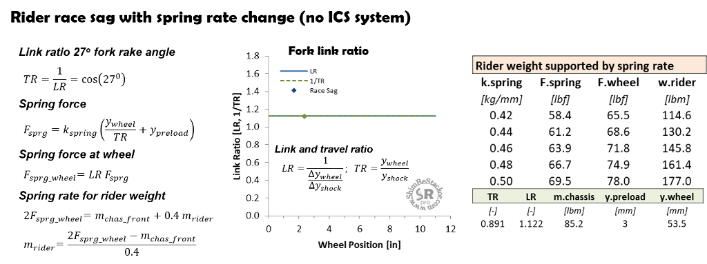
Spring force on the shock shaft is determined by inputs of the spring constant k.spring [kg/mm], spring preload and shock shaft position. Travel ratio (TR) specifies the relationship between wheel position and shock shaft position.
For a fork, travel ratio is constant through the stroke and defined by the fork rake angle.
On a shock, the value of travel ratio changes through the stroke and is determined from inputs of wheel and shock shaft position (more). That same process can be used on a fork if the rake angle is unknown.
The equations below define rider weight as a function of spring rate, link ratio, front chassis weight and race sag.
Fork ICS spring
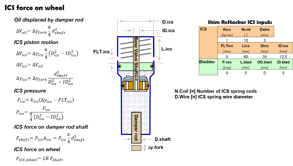
As a fork is compressed, the volume of oil displaced by the damper rod is forced out of the shock into the ICS oil reservoir. The displaced oil compresses the ICS piston and spring, which back pressures the fork chambers to suppress cavitation.
The combination of pressure from the ICS and damper rod area defines the ICS force on the shock shaft. Link ratio defines transfer of that force to vertical force on the front wheel.
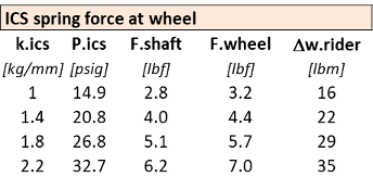
An ICS pressure of 14.9 psig delivers 3.2 lbf to the front wheel. For two fork legs, the combined force is 6.4 lbf. With 40% of the rider weight on the front wheel a rider weight increase of 16 lbm is needed to match the 3.2 lbf force from the ICS pressure.
ICS spring preload
An ICS spring preload of 14 mm on a 1.4 kg/mm spring increases the front wheel force by 8.1 lbf creating a 40 lbm increase in rider weight. Effects of the ICS system are often overlooked in estimating spring rates and the effect can be substantial.
Fork gas force
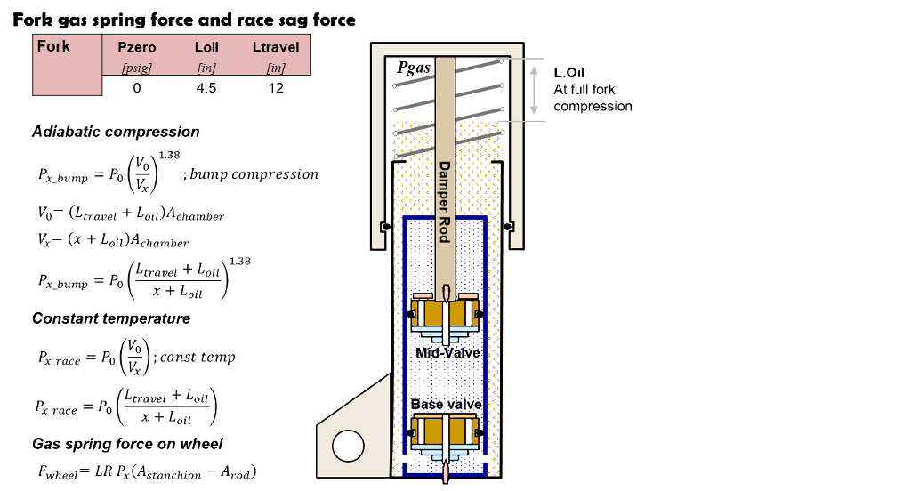
When gas is compressed both the pressure and temperature increase through a process known as adiabatic compression. If the compressed gas sits for a couple of seconds the gas temperature dissipates into the chamber wall. The drop in temperature lowers the gas pressure giving a process known as constant temperature compression.
Both processes occur in suspensions. On bump motions, the suspension compresses and returns in 0.1 seconds giving no time for the gas temperature to dissipate. Gas pressure during bump motions is defined by adiabatic compression.
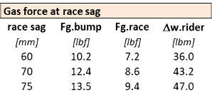
When measuring race sag, the suspension compresses to the race sag position and sets there allowing the compressed gas temperature to dissipate into the fork body. The gas force at race sag is defined by constant temperature compression.
Shim ReStackor rider weight calculations compute gas force using constant temperature compression. Bump calculations use adiabatic compression giving a slightly higher gas force.
Seal drag
Stiction in race sag measurements gives a direct measurement of seal drag.
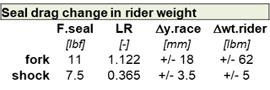
Lifting the bike slightly and allowing the suspension to fall back to race sag; or pushing the bike down and allowing the suspension to rise to race sag quantifies seal drag. The difference in race sag positions are typically 18 mm for a fork and 3.5 mm for a shock.
The 3.5 mm stiction zone for a shock creates a rider weight uncertainty of +/- 5 lbm. On a shock, link ratio reduces the seal drag effect allowing accurate race sag measurements.
Seal drag on a fork typically runs around 11 lbf creating 22 lbf of stiction for two fork legs. When combined with link ratio and 40% of the rider weight on the front wheel the uncertainty in rider weight becomes +/- 62 lbm.
The +/- 62 lbm uncertainty in race sag weight makes measurement of a 180 lbm rider nearly impossible, which is why many tuners have given up measuring fork race sag as a method to specify the needed spring rate.
Fork race sag
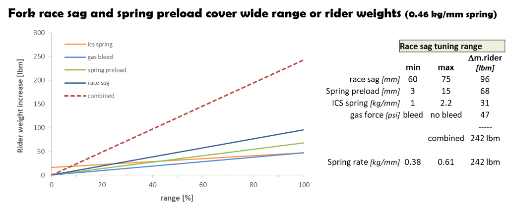
The tuning range for fork spring preload, bleed pressure and ICS spring rate each create a rider weight change of approximately 50 lbm. Increasing stanchion tube sag from 60 to 75 mm increases rider weight by 96 lbm. Combining all of those effects increases the rider weight by 242 lbm. That is equivalent to increasing the fork spring rate from 0.38 to 0.61 kg/mm.
When spec’ing fork spring rates the ICS spring rate, preload and gas bleed pressure make a big difference.
"Rule of thumb" fork tuning range covers 242 lbm change in rider weight
Fork spring rate range
The fork spring force at race sag is composed of five components:
- Fork spring stiffness
- Fork spring preload
- Gas force
- ICS spring stiffness
- ICS spring preload
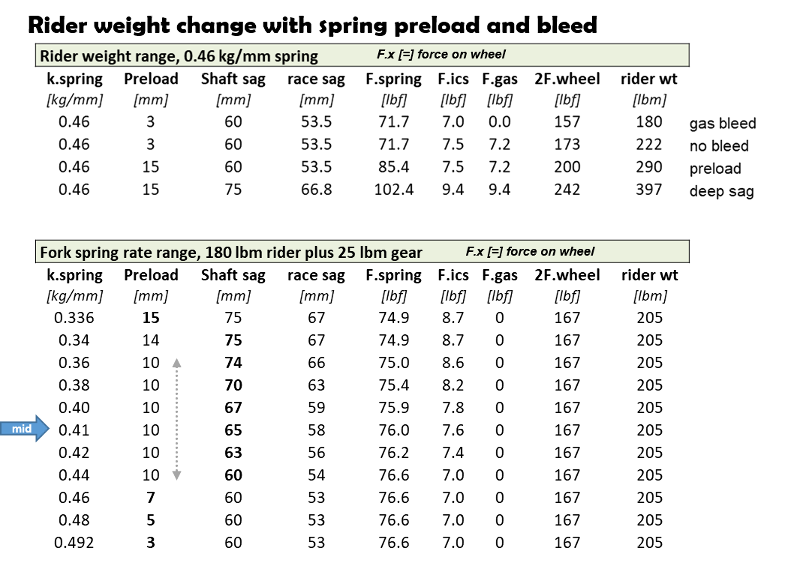
With a fixed ICS spring rate of 2.2 kg/mm and zero ICS spring preload, the target range of bleed, spring preload and race-sag covers a wide range of weights from 180 to 397 lbm as shown by the Shim ReStackor response calculations below.
Spring rate calculators specify a specific spring for a given rider weight. However, when the spring rate is combined with the recommended range of preload from 3 to 15 mm and race sag of 60 to 75 mm the spring rate recommendation covers a huge range of rider weights.
Spring calculators get you in the ballpark. Final selection is based on how the bike rides:
- If the suspension riders too stiff, you need a softer spring
- If the suspension bottoms too easily, you need a stiffer spring
Increasing race sag from 20% to 25% allows wide range of fork spring rates
Shock spring rate range
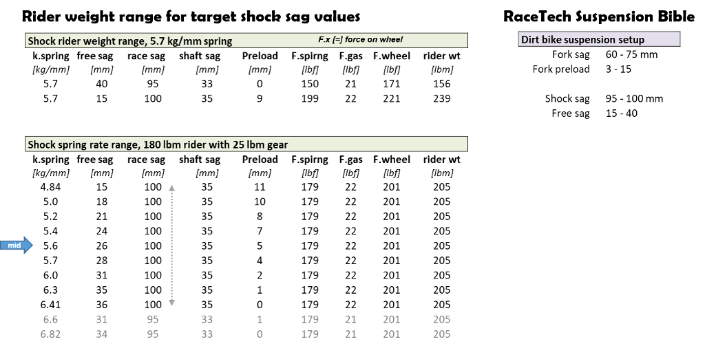
The RaceTech Suspension Bible provides a recommended range of spring preload, free sag and race sag for dirt bikes. For a 5.7 kg/mm spring, the recommended range covers rider weights from 156 to 239 lbm as the Shim ReStackor suspension response calculations below show.
For a fixed rider weight of 205 lbm, spring rates from 4.9 to 6.8 kg/mm all fall within the recommended free-sag and race-sag range.
The wide range of spring rates hitting spec values of free sag and race sag emphasizes rider preference is a critical part of selecting the spring used.
Spring rate selection
Spring rate calculators give reliable spring rate recommendations that put you somewhere in the midrange of tuning values. However, the recommended range of free-sag, race-sag and spring preload allow a wide range of spring rates to be used.
The final selection is entirely based on rider preference and how the bike rides. If the suspension rides too stiff, or has poor ground compliance, you need a softer spring.
If the suspension bottoms, you need a stiffer spring.
Covering up a soft spring with stiff compression damping gives slow rebound response causing the suspension to pack. Likewise, compensating for a stiff spring with soft compression damping gives less than optimum bump compliance.
Optimizing the setup requires the right combination of spring rate and damping. Ground compliance on an enduro setup requires rebound/compression damping ratios in the 2 to 2.5:1 range for a shock. Jump landing bottoming control on a MX setup requires substantially stiffer compression damping resulting in compromised bump compliance (more).

