An important but little known fact is shock absorber oil contains 10% by volume dissolved gas (nasa). Gas reservoirs pressurized to 147 psi allow nitrogen to slowly diffuse through the bladder, or around the o-ring seals of a piston reservoir, and saturate the oil with dissolved nitrogen after about 4 months.
When expanded back to atmospheric pressure, 10% by volume at 147 psi (10 atm) becomes 100% by volume severely foaming the oil.
Dissolved gas makes the oil in shock absorbers behave like a hot bottle of coca-cola. Keep the cap on and the fluid behaves like a liquid. Crack the cap and the drop in pressure allows the dissolved gas to boil out making the fluid a foamy mess.
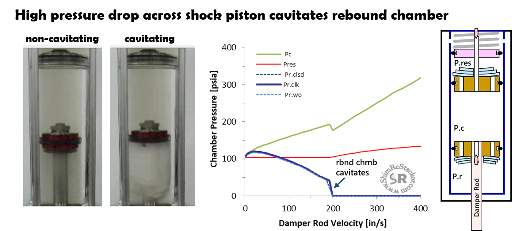
Roehrig made a video to demonstrate the severity of cavitation oil foaming. On the compression stroke the pressure drop across the mid-valve forces pressures in the rebound chamber to drop.
When the rebound chamber pressure drops below the dissolved gas pressure the dissolved gas boils out and foams the oil.
When the shock flips around into the rebound stroke, the piston just wings back through the foamed out oil producing zero rebound damping force. The problem with cavitation isn’t loss of compression damping, it is loss of rebound. That shows up as a squishing noise.
The fix for cavitation is simple. The shock compression adjuster, or fork base valve, needs to backpressure the shock chambers and keep the chambers pressurized, at or above the gas reservoir pressure, across the entire range of shock absorber stroke velocities. Keeping the shock chambers pressurized is equivalent to keeping the cap on a hot bottle of coca-cola.
Tuning shocks to control pressures in the rebound chamber is known as “pressure balancing” the shock. Shim ReStackor makes that easy.
Shock absorber pressure balancing
Shim ReStackor calculations compute the pressure in each chamber of the shock. Pressure balancing simply requires hacking around on the fork base valve shim stack, or compression adjuster on a shock, to keep the rebound chamber pressure (blue line) at or above the gas reservoir pressure (red line).
At zero velocity, the fork ICS system compressed to race sag pressurizes the fork oil reservoir to 100 psi (red line). At low shaft velocities, the rebound chamber pressure initially rises due to back pressure from the fork base valve coupled with float on the mid-valve producing little pressure drop.
As speeds increase to 70 in/sec the pressure drop across the mid-valve matches the back pressure from the base valve forcing the blue and red lines to match at the initial 100 psi oil pressure.
As the fork is pushed beyond 70 in/sec the pressure drop across the mid-valve increases faster than the backpressure from the base valve forcing pressures in the rebound chamber to drop below 100 psi. At that point, gas dissolved in the fork oil will begin to boil out and foam the shock oil.
At 200 in/sec the base valve does not produce enough back pressure to force the required oil flow through the mid-valve. At that point, pressures in the rebound chamber drop to zero forming a vacuum bubble behind the mid-valve and severely foaming the oil in the rebound chamber.
“Pressure balancing” the shock to suppress cavitation oil foaming simply requires hacking around on the fork base valve or compression adjuster shim stack to keep the blue line (rebound chamber pressure) at or above the red line (reservoir pressure) across the shock absorber shaft velocity range.
Pressure balance tuning
The above example needs more backpressure from the base valve to pressure balance the shock. To get more backpressure, the base valve shim stack clamp diameter and stack taper stiffness was increased. With more damping force from the base valve the mid-valve was softened to keep the overall compression damping force the same.
With the stiffer base valve, the fork can now be pushed to 400 in/sec without cavitating the rebound chamber.
Suppressing cavitation oil foaming allows the shock piston to always move through clean un-foamed oil to give consistent damping performance across the entire range of suspension velocities and stroke frequencies. Suppressing cavitation fixes the hysteresis curves frequently seen shock absorber dyno testing.
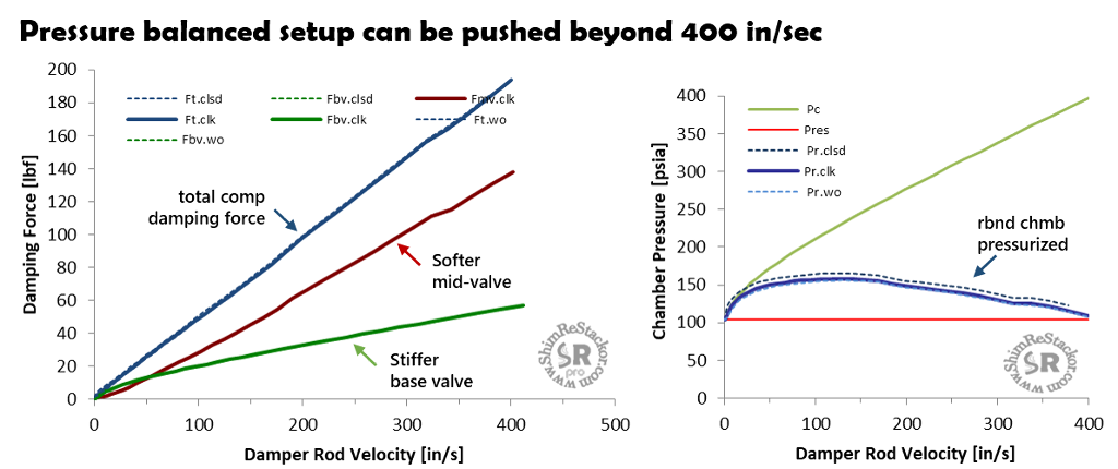
Ideally, a pressure balanced shock maintains pressures in the rebound chamber at the initial gas reservoir pressure. Matching the gas reservoir pressure is the minimum requirement to prevent gasses dissolved in the oil from boiling out. Tuning to that minimum requirement also reduces wear on the shaft seals.
However, shock absorbers typically produce rebound damping forces that are double the value of compression. For the above example, the shock produces peak rebound chamber pressures of 500 psi at the maximum rebound stroke velocity and the shaft seals are designed to operate at those pressures.
Suppressing cavitation oil foaming requires tuning the compression valving to maintain pressures in the rebound chamber at or above the initial gas reservoir pressure. The above example exceeds that minimum by 50 psi at velocities around 120 in/sec. The 50 psi overpressure is well within the operating limits of the shock set by peak pressures in the rebound stroke.
Dyno tuning "rules of thumb"
A dyno tuning “rule of thumb” is the compression adjuster should produce about 12% of the overall damping force. Some say that rule is established to give riders required tuning range when adjusting the high speed compression adjuster.
In reality, the 12% “rule of thumb” is a requirement for suppression of cavitation. Stepping through some algebra shows that.
The damping force from the base valve, or compression adjuster in a shock, is equal to the base valve pressure drop times the damper rod area.
The total damping force is the base valve force plus the mid-valve swept area multiplied by the pressure drop across the mid-valve.
On a “pressure balanced” shock the base and mid-valve pressure drops match. The matched pressure drop requirement reduces the equation to the ratio of damper rod to mid-valve diameter squared.
For the special case of a 16 mm damping rod and 46 mm shock piston the 12% “rule of thumb” pressure balances the shock, but only for that specific configuration.
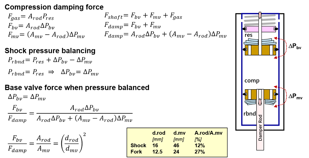
On a fork with a 24 mm mid-valve and a 12.5 mm damper rod a damping force ratio of 27% is required to pressure balance the shock.
The 12% “rule of thumb” works for a shock. But applying that same rule to a fork will severely cavitate the fork chambers. There is no universal rule. The damping force required from the compression adjuster, or fork base valve, changes depending on the damper rod and shock valve diameter.
Shim ReStackor makes pressure balancing the shock easier. The single requirement of pressurizing the rebound chamber at or above the gas chamber pressure suppresses cavitation for all configurations regardless of the damper rod or shock piston diameter. The single rule eliminates the confusion that sometimes tricks dyno tuners into tuning everything to the 12% "rule of thumb" and severly cavitating the shock.
Cavitation and oil foaming control
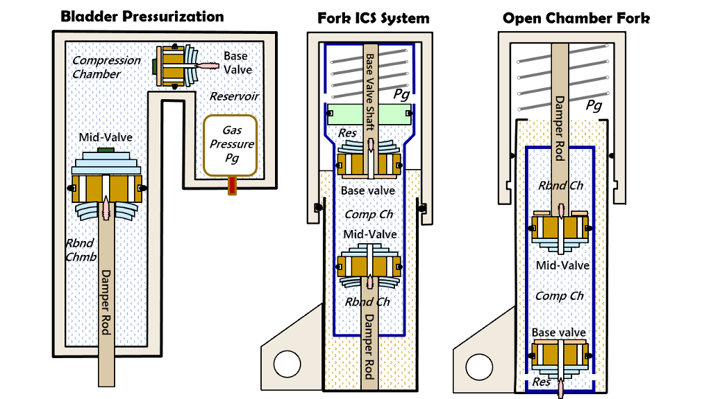
Pressure balancing shock chambers is a necessary step for tuning forks and shocks to suppress cavitation oil foaming. On a fork, the base valve controls backpressure. On a shock, the compression adjuster controls backpressure. Twin tube shocks replace the compression adjuster with the chamber foot valve.
Regardless of naming conventions, suppressing cavitation requires tuning the shock circuits to keep all of the chambers pressurized at or above the gas reservoir pressure across the entire range of suspension velocities. Direct calculation of chamber pressures in Shim ReStackor makes that process easy.