
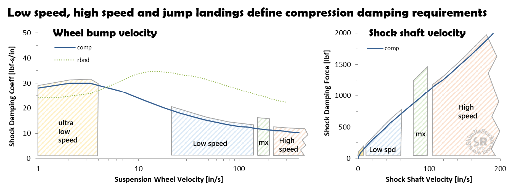
Suspension valving theory sets four damping targets for compression damping tuning of shock absorber compression shim stacks:
- Ultra-low speed: Catch rebound overshoot and hold the suspension “high in the stroke"
- Rebound/compression damping ratio of 0.8:1
- Low speed: Small bump compliance to improve wheel traction
- Compression damping force less than bike weight
- MX jump landing bottoming resistance
- Stiff compression damping at suspension speeds of 150 to 180 in/sec
- High speed: Chassis deflection off three inch and larger bumps
- Compression damping force matches spring force above 200 in/sec
Bump compliance requires soft compression damping allowing the high speed suspension motions needed for the wheels to clear obstacles and prevent chassis deflection.
Jump landing bottoming resistance requires stiff compression damping to absorb the combined chassis plus rider weight on ground impacts.
Compression damping compromise
Stiff compression damping required for motocross jump landings conflicts with the soft damping required for suspension compliance. The conflict forces a compromise, which defines the difference between motocross jump landing setups and the softer damping required for trail and enduro ground compliance.
Shim ReStackor suspension response calculations quantify low speed, high speed and jump landing bottoming resistance allowing tailoring of the damping force curve to meet the specifics of the application at hand.
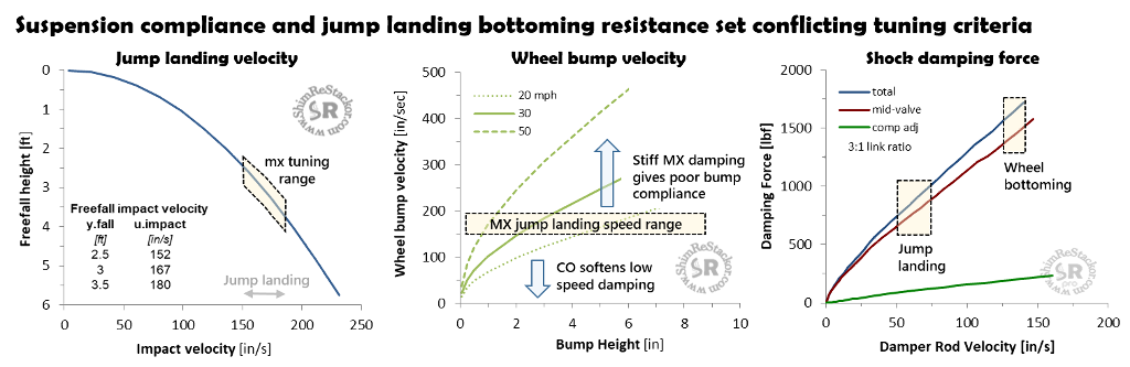
Bump compliance versus bottoming resistance
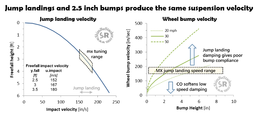
Gravity dictates jump landing impact velocities. A three foot jump freefall produces an impact velocity of 167 in/sec. A wheel rolling over a 2.5 inch bump at 30 mph produces the same 167 in/sec suspension velocity (more).
Jump landings or a 2.5 inch bump produce the same suspension velocity. Damping stiff enough to absorb jump landings will cause the chassis to deflect off a 2.5 inch bump.
That fact forces a suspension compromise to either focus on the stiff damping required for jump landings or the softer damping required for bump compliance.
Enduro suspension setup
Enduro setups are not competitive if the bike cannot make a hill climb. Bump compliance on two inch roots and rocks requires light compression damping allowing the high speed wheel motions necessary to clear the obstacle. Bump compliance keeps the wheels on the ground generating the traction needed to make a hill climb. Enduro setups tuned for ground compliance will bottom on small jumps.
Motocross suspension setup
MX setups are not competitive if the bike cannot land a jump. Jump landings require stiff compression damping in the 150 to 200 in/sec range. Damping stiff enough to absorb the combined bike plus rider weight on jump landings will causes the chassis to deflect off two to three inch bumps producing the same 150 to 200 in/sec compression stroke velocity.
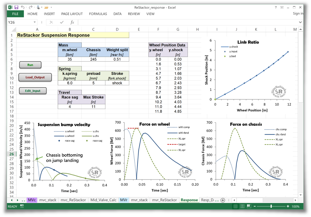
Jump landing tuning
Shim ReStackor suspension response calculations compute the ground impact velocity required for the combined bike plus rider weight to drive the suspension from full extension to the stroke depth specified by the “Max Stroke” input. The example below evaluates an 11 inch stroke that bottoms the chassis at an impact velocity of 155 in/sec.
Tuning compression damping to absorb jump landings is straight forward:
- Lookup the impact velocity produced by the jump height
- Hack the compression damping shim stack to absorb the target impact velocity
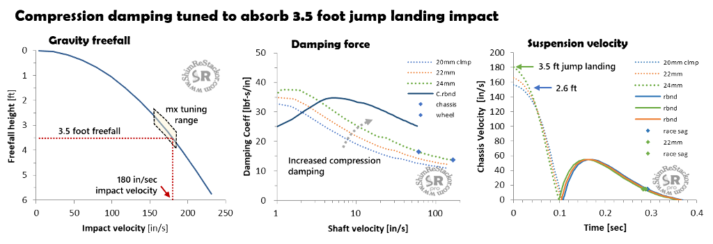
Jump landing impact velocity
Gravity dictates impact velocities on jump landings. A 3.5 foot freefall produces an impact velocity of 180 in/second (more).
Bottoming control
The baseline shim stack with a 20 mm clamp bottoms an 11 inch stroke at an impact velocity of 156 in/sec, equivalent to a 2.6 foot jump height freefall.
Increasing the shim stack clamp diameter from 20 to 24 mm increases the chassis bottoming velocity from 156 to 178 in/sec. Adding an additional face shim hits the target 180 in/sec impact velocity needed for a 3.5 foot jump freefall.
MX suspension shim stack tuning to control jump landing bottoming
Acceleration traction
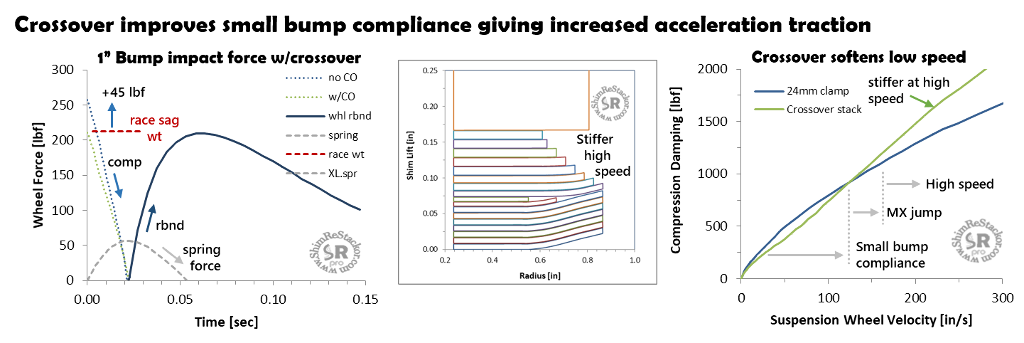
To win drag races out of corners the suspension needs good small bump compliance. Compression damping forces greater than the bike weight pop the chassis up and unweight the wheels causing a loss of traction.
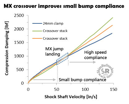
Running the above shim stack configuration tuned for a 3.5 foot jump landings on a one inch wheel bump stroke produces a compression damping force 45 lbf greater than the bike race sag weight on wheel. The stiff compression damping pops the chassis up and unweights the wheels causing a loss of traction.
Adding a crossover to the compression shim stack reduces the low speed compression damping force and improves small bump compliance. In the example, adding a crossover reduces the compression damping force (green line) on a one inch bump to match the bike race sag weight.
With the crossover add, the shim stack requires a stiffer high speed stack to maintain the same jump landing bottoming resistance. When the stiffer high speed stack is pushed beyond the 180 in/sec jump landing speed, the stiffer high speed stack increases the high speed compression damping force causing the chassis to deflect off high speed braking bumps.
Acceleration traction trade
The above example illustrates a fundamental suspension tuning trade:
- Running a digressive shim stack without a crossover gives good high speed compliance, but poor compliance on low speed bumps below 100 in/sec
- The crossover improves small bump compliance, but the progressive damping force curve gives poor high speed compliance above 150 in/sec
- A softer compression shim stack improves both low and high speed bump compliance, but the softer compression damping compromises jump landing bottoming resistance
Motocross suspension setups for hard pack conditions gain low speed bump compliance and wheel traction using a crossover. However, the progressive damping force curve created by crossovers produces harshness and chassis deflection on high speed braking bumps.
Shim ReStackor suspension response calculations quantify the low speed, high speed and jump landing bottoming resistance allowing the compression damping curves to be bent around to produce the best compromise between low and high speed bump compliance, and bottoming resistance on jump landings.
Bleed systems, stack float, stack stiffness, crossover gap height, diameter and position control low speed damping, and the suspension bump velocity where damping force becomes greater than the bike weight forcing the chassis to deflect off bump impacts.
Motocross suspension setup to improve acceleration traction
Ultra-low speed damping
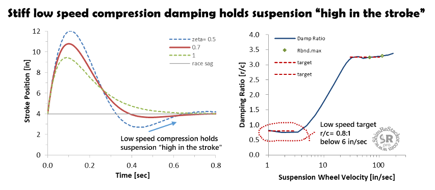
Rebound damping at zeta values of 0.7 is underdamped (more). Underdamped means the suspension will overshoot race sag and baby-buggy back. Baby-buggy motions give a loose, uncontrolled, suspension “feel”.
Tuners have a trick to suppress the baby-buggy motions caused by underdamped rebound.
Rebound overshoot returns back to race sag through an ultra-low speed compression stroke at speeds below 6 in/sec (more). Stiff compression damping at ultra-low speed “catches” the rebound overshoot, holds the suspension “high in the stroke” and heavily damps the return stroke to stop baby-buggy motions and quiet the suspension at race sag.
Suppressing baby-buggy motions using low speed compression damping requires rebound/compression damping ratios of 0.8:1 below suspension speeds of 6 in/sec.
Stiff compression damping at ultra-low suspension speeds has no impact on suspension bump compliance or harshness. A 1/125 inch bump hit at 20 mph produces a suspension bump velocity of 6 in/sec. Tire compliance completely consumes bumps that small.
Larger bumps, in the ¼ inch range, produce suspension speeds above 30 in/sec at 20 mph. Tuning compression damping to blow-off low speed above velocities of 6 in/sec provides the stiff compression damping needed at ultra-low speed and bump compliance for anything larger than 1/125 of an inch.
Forks provide multiple systems for controlling low speed compression damping: Mid-valve check springs, base valve bleed, stack stiffness, rebound separator valve or the low speed shim stack (LSV) on the base valve bleed circuit.
On a shock, the compression shim stack, clicker bleed, compression adjuster low speed circuit or rebound separator valve set compression damping at ultra-low suspension speeds (more).
High speed compliance
Conflicting requirements of jump landing bottoming resistance and suspension bump compliance set the stiffness of high speed compression damping:
1: Bump compliance
Compliance on roots, rocks or braking bumps requires light compression damping to allow the high speed wheel motions necessary to clear the obstacle. Stiff compression damping resisting high speed suspension motions causes the chassis to deflect off bumps.
Spring rate sets the suspension compliance limit. Bumps compressing the fork to four times the race sag ride height produce four times the race sag spring force. Four times the spring force produces a chassis g-force of 3g (4-1g). Reducing chassis deflection on deep strokes requires soft springs run at high preload.
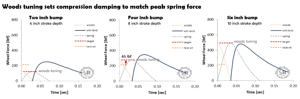
Setting compression damping to match the peak spring force sets the bump impact g-force to match the peak spring g-force. Matched peak force produces a more-or-less constant force through the stroke with compression damping dropping off as the spring force ramps up. Constant force through the stroke absorbs the maximum bump energy while delivering the minimum g-force to the chassis, set by the suspension spring rate.
The example below tunes compression damping to match the peak spring force at stroke depths of two, four and six inches. The four inch stroke produces a peak spring force that is 65 lbf higher than the bike race sag weight. Suspension forces greater than the bike weight causes the chassis to deflect off the bump. Reducing bump deflection for the setup requires the use of a softer spring.
2: Bump energy dissipation
Second approach: A suspension tuning “rule of thumb” is the ratio of rebound/compression damping should be approximately 2:1 measured on a dyno at the same shaft speed. That makes it sound like rebound damping produces more force than compression. It does not.
The highest suspension velocities occur at bump impact. High suspension velocities in the compression stroke produce high compression damping forces. On rebound, damping fights against the spring force producing lower suspension velocities and lower rebound damping force.
When installed in a suspension, a damping ratio of 2:1 produces compression damping forces that are approximately equal to the peak rebound damping force. Equal damping force in both directions gives the suspension a symmetric “feel”.
Equal peak force also sets the force times distance work done in compression to be approximately equal to the work done in rebound. Equal work dissipates half of the bump energy in compression and the second half in rebound.
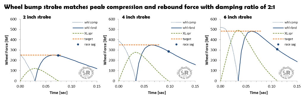
For automotive and motorcycle suspensions running 33% race sag the 2:1 damping ratio “rule of thumb” produces equal peak forces in compression and rebound.
Motorcycle forks running 25% race sag have a longer stroke to bottoming. The longer stroke requires higher bump speeds, which increases the force from compression damping. The equal peak force “rule of thumb” on the longer stroke of a fork requires a damping ratio near 3:1.
3: Bottoming control
Controlling suspension bottoming is straight forward:
- Determine the ground impact velocity for the target jump height
- Hack compression damping to absorb the target impact
Jump heights from 2.5 to 3.5 feet produce impact velocities from 152 to 180 in/sec. Bottoming control requires stiff compression damping through the 152 to 180 in/sec range to absorb jump landings.
Bumps of 2.5 inches hit at 30 mph and three foot jump landings produce the same 167 in/sec compression stroke velocity. Compression damping stiff enough to absorb jump landings will deflect the chassis off 2.5 inch bumps.
That fact forces compression damping tuning to either absorb jump landings or provide bump compliance. The suspension cannot do both.
Adding a crossover to the compression shim stack slightly reduces low speed compression damping and improves small bump compliance and wheel traction. However, the progressive damping force curve inherent with a crossover increases high speed damping making the suspension harsh on high speed braking bumps and causes chassis deflection off root and rock impacts.
Eliminating the crossover to run a simple tapered shim stack produces a digressive damping force curve. The compression damping roll-off at high speed improves high speed braking bump compliance. However, the digressive curve increases damping force at low speed causing poor small bump compliance creating acceleration traction problems.
Tuning compression damping to absorb jump landings requires compromising low or high speed bump compliance.
High speed compression damping
One of three criteria set high speed compression damping:
- Bump compliance
- Equal energy dissipation
- Jump landing control
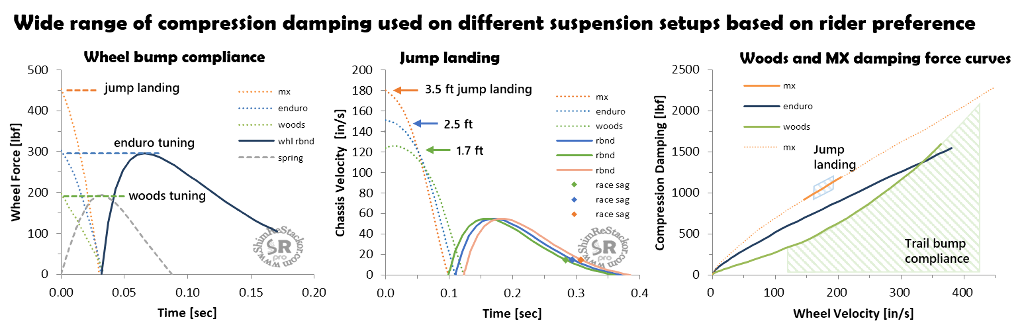
Woods bikes focus on ground compliance using soft compression damping just stiff enough to control motions of the 35 lbm wheel. Motocross setups require stiff compression damping for jump landings and the stiff damping forces chassis deflection off high speed bumps. Those two extremes cover a wide range of high speed compression damping.
Response calculations quantify jump landing bottoming resistance, small bump traction compliance and chassis deflection off high speed bumps. Quantifying those three limits helps to make smart tuning decisions in balancing the three extremes. Rider preference compromising jump landing bottoming resistance against ground compliance sets the balance.
Compression damping tuning
Four tuning targets set compression damping:
- Ultra-low speed: Catch rebound overshoot and hold the suspension “high in the stroke"
- Rebound/compression damping ratio of 0.8:1
- Low speed: Small bump compliance to improve wheel traction
- Compression damping force less than bike weight
- MX jump landing bottoming control
- Stiff compression damping at suspension speeds of 150 to 180 in/sec
- High speed: Chassis deflection off three inch and larger bumps
- Compression damping force matches spring force above 200 in/sec
No single criterion sets the stiffness of compression damping. Instead, a series of compromise between low speed bump compliance for wheel traction, jump landing bottoming resistance and chassis deflection off braking bumps, root and rock impacts sets the balance. Perfecting performance is entirely based on rider preference.
Perfecting the balance requires relentless fine tuning continuously reworking the trade between bottoming resistance, high speed bump compliance and wheel traction. Shim ReStackor streamlines that process evaluating the effect of potential shim stack modifications on each of the limits allowing tuning to focus on modifications that only effect low speed, high speed or jump landing bottoming resistance.
Fine tune suspension setups far beyond the limits previously possible