Viscosity
Suspension oil viscosity is specified in terms of kinematic viscosity (cSt@40c) defined as the actual viscosity (aka dynamic viscosity) divided by the oil density.
The kinematic viscosity definition as the ratio of viscosity to density creates some confusion in oil property effects that few understand.

Shock absorber damping force depends on both oil viscosity and density:
- High viscosity oils increase flow friction losses and damping force
- High density oils require more force to push the heavier fluid through flow restrictions also driving damping force up
A high density oil will produce more damping force, but the value of kinematic viscosity will be lower due to the definition of viscosity/density.
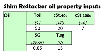
By itself, kinematic viscosity means nothing. The damping force produced by an oil depends on both viscosity and density, which is why Shim ReStackor uses separate inputs for both.
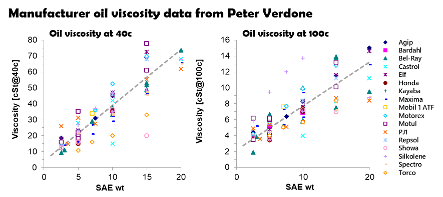
Brand-to-Brand suspension oil viscosity differences complied by Peter Verdone
Oil density
Oil density varies by 15% from brand-to-brand. High density oils produce more damping force because the fluid is heavier. A high density oil with the same kinematic viscosity will further increase damping force because the viscosity is also higher due to the kinematic definition of viscosity/density.
Oils with the same value of kinematic viscosity will produce different damping forces because of differences in oil density.
By itself, the kinematic viscosity printed on the side of the bottle means nothing without knowing the density.
For suspension tuning, specifying the true oil dynamic viscosity in centipoise (cP) and density would be a better oil specification.
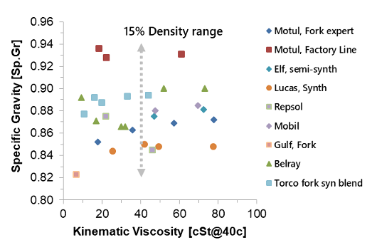
Suspension oil density varies by 15% from brand-to-brand
Kinematic viscosity becomes even more confusing when comparing different fluid circuits. Most suspensions use a simple conical needle in the clicker circuit. High fluid acceleration at the throat makes tapered needles sensitive to fluid density.
Other bleed circuits use friction needles. Friction needles have a small needle taper. Screwing the needle in increases the length of the high velocity throat region, which increases the viscous friction losses. Friction needles are sensitive to oil viscosity and relatively insensitive to density.

The two fluid dynamic properties of oil viscosity and density effect fluid circuits in different ways. Both effects must be evaluated to determine the effect of oil property changes on damping performance.
Shim ReStackor makes those calculations and accounts for brand-to-brand differences in oil properties on damping performance.
Temperature effects on oil viscosity
ReStackor evaluates the falloff in oil viscosity with temperature using a modified form of the Andrade equation. Manufactures specify oil properties at two temperatures cSt@40C and cSt@100C. Combined with oil density, those properties define the true dynamic viscosity and the coefficients of the Andrade equation needed to evaluate temperature effects on oil viscosity.
The oil viscosity computed by Shim ReStackor exactly matches the manufacture specs at 40 and 100 C and includes a low temperature viscosity pour point correction, T.frz. The Andrade equation defines oil viscosities at intermediate temperatures between the manufacture specs and accurately scales viscosities to temperatures beyond the spec range.

The Viscosity Index (VI), defined by ASTM D 2270-04, relates the viscosity of an oil at 40C and 100C to the viscosity of a reference “good” oil.
Manufactures use VI as a simple reference of oil quality. Oils with a high VI index have a lower viscosity change with temperature.
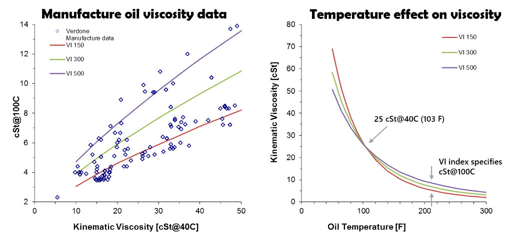
High VI oils produce a lower viscosity drop-off with temperature. However, it is important to understand oil viscosity significantly falls-off with temperature regardless of the VI index as demonstrated in the the above figures.
Oil viscosity changes with temperature create problems for dyno tuners. A shock that generates 1,000 lbf of damping force at 100 in/sec heats the oil at a rate of 32 oF/sec.
Changing the dyno test duration by a couple of seconds, significantly changes the oil temperature, reducing the oil viscosity and damping force measured in the test. That creates run-to-run differences in the test data and creates difficulties comparing back-to-back tests evaluating different shock absorber configurations.
Suspension oil manufactures don’t report the compressibility of suspension oils. However, the effect can be estimated using standard hydraulic system design “rules of thumb”. In hydraulic systems, oil compressibility results in a volume reduction of 1/2% at 1000 psi, engineers edge.
On a fork, with a compression chamber length of 13 inches, a sudden spike in pressure to 500 psi would allow the fork to move 0.03 inches due to the 1/4% volume change of oil compressibility at 500 psi. The uncontrolled motion is known as surge in hydraulic systems, and the effect is small.
In reality, deflection of seals, expansion of the shock chamber and compressibility of foamed oil are larger effects. Hydraulic oils are, by design, virtually incompressible.
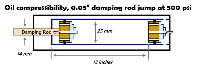
Suspension oil compressibility produces little effect in suspension systems
Hydraulic fluid vapor pressure
Cavitation in hydraulic circuits is dictated by the fluid vapor pressure and gasses dissolved in the suspension oil. Shim ReStackor computes fluid vapor pressure using the Antoine equation to determine the effect of oil temperature increases under race conditions.
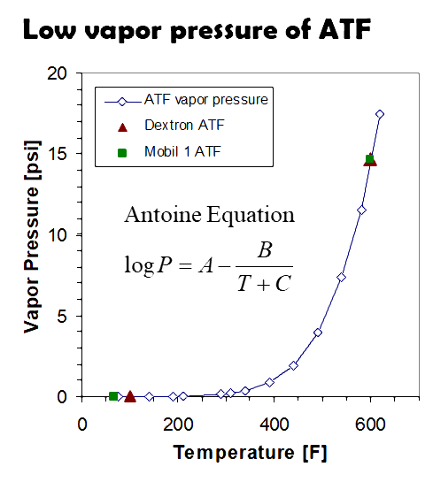
The material safety data sheets available for Mobil 1 ATF gives the vapor pressure at the normal boiling point and at atmospheric conditions. Chevron provides similar data for Dextron automatic transmission fluid.
The combined data provides an estimate of suspension oil vapor pressure. At the normal boiling point of water (212 F) the vapor pressure of ATF is less than 0.1 psi. At temperatures around 600 F the vapor pressure approaches atmospheric pressure.
By design, the vapor pressure of suspension fluid is very low. As long as the shock oil is below the boiling point of water (212 F) the typical assumption of zero vapor pressure is reasonable for evaluating cavitation limits.
Gases dissolved in the suspension oil is by far the bigger issue in evaluating cavitation limits.
Oil density
The ATF data also specifies the oil density change with temperature. Oil density drops by approximately 6% with a 100 C increase in oil temperature. The density change is linear over that range.
In practical applications, the effect of hot oil in reducing the spring stiffness of shims is a larger effect than the effect of temperature on oil density. Shim ReStackor calculations account for both effects when evaluating oil temperature changes.
Gas dissolved in suspension oils
A fresh bottle of factory sealed suspension oil contains 10% by volume dissolved gas. Pull a vacuum on the oil and the dissolved gas boils out causing the oil to foam as demonstrated by the photo below from Ride Concepts, Calgary.
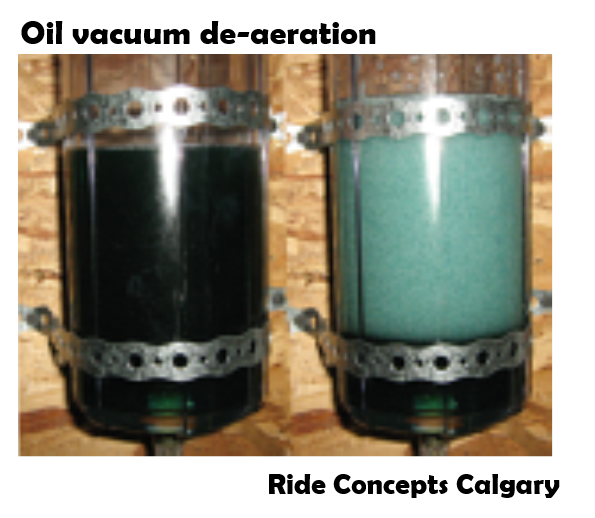
Gasses dissolved in liquids are measured by an Ostwald coefficient defined as the volume fraction of gas dissolved in the liquid. For suspension oils the Ostwald coefficient is around 10% for nitrogen.
When the shock gas reservoir is pressurized to 147 psi the nitrogen in the reservoir will diffuse through the shock bladder, or around the o-ring seals of a piston reservoir, and saturate the oil with dissolved gas at 10% by volume over the course of about four months. Ten percent dissolved gas under pressure at 147 psi means the oil contains 100% dissolved gas by volume when the pressurized gas is expanded back to atmospheric pressure.
Dissolved gas in suspension oils make the oil behave like a hot bottle of coca-cola. When the oil is under pressure the oil behaves like a liquid. Crack the cap and the drop in pressure allows the dissolved gas to boil out making the fluid a foamy mess.
Shock pressure balancing
Suppressing cavitation with gas dissolved in the oil requires “pressure balancing” the shock. Pressure balancing is the simple process of tuning compression adjusters, or fork base valves, to backpressure the shock chambers and keep pressures at or above the dissolved gas pressure, set by the gas reservoir pressure. Keeping the shock chambers pressurized is equivalent to keeping the “cap on” a hot bottle of coca-cola.
Shim ReStackor makes pressure balancing is easy. The calculations compute pressures in each chamber of the shock. Pressure balancing the shock simply requires hacking around on the compression adjuster, or fork base valve, to keep the rebound chamber pressurized at or above the gas reservoir pressure across the stroke velocity range (more).
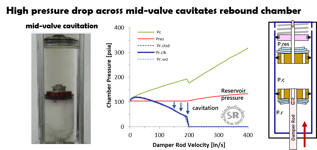
Pressure balancing the shock requires tuning of compression adjusters and fork base valves to keep the rebound chamber pressurized on the compression stroke
Shim ReStackor oil properties
Inputs of the shock operating temperature, oil kinematic viscosity at two temperatures and oil density at the input reference temperature specify oil properties in Shim ReStackor inputs.
The Andrade equation is used to correct viscosity for temperature changes, the Antoine equation to correct vapor pressure, Ostwald coefficients to account for dissolved gas with additional corrections for temperature effects on oil density and shim stiffness.
Physics based oil property corrections for the effect of pressure and temperature allow Shim ReStackor calculations to accurately scale fluid dynamic effects across the entire range of shock absorber operation velocities.
