Linked suspension systems change the ratio of wheel to shock motion and that ratio continuously changes through the stroke.
The two parameters Travel ratio and Link ratio describe the change in motion and transfer of force through linked suspension systems.
Travel ratio (TR)
Travel ratio is the ratio of wheel to shock shaft position. Travel ratio defines how far the spring is compressed at a given wheel position, which defines the spring force.
Link ratio (LR)
Link ratio defines the change in shock shaft position for a minute micro motion of the wheel. Link ratio defines how fast the shock shaft moves and that defines damping force.
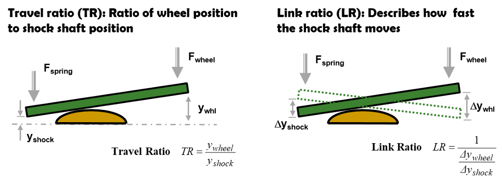
Link ratio and travel ratio define the motion and force transfer through linked suspension systems
Travel ratio defines the shock shaft position. Link ratio defines the shock shaft velocity. The two ratios are similar but the numerical values are different as the graph below shows. Shim ReStackor response calculations compute the suspension link ratio and travel ratio from inputs of measured wheel and shock shaft position.
Measuring the wheel and shock shaft positions through the stroke provides a simple and direct method to determine the suspension link ratio and an easy way to compensate for year-to-year changes in suspension setups or the use of custom aftermarket link arms or knuckle geometries.
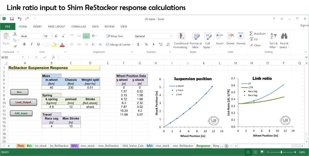
Response calculations compute link ratio from measured inputs of wheel and shock shaft position
Spring force at wheel
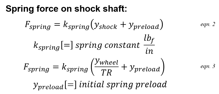
To get spring force at the wheel, the first step is figure out how far the spring is compressed when the wheel is moved to a specified stroke position y.wheel. Travel ratio defines the relationship.
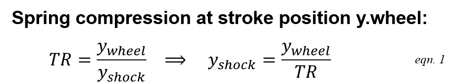
The spring constant and initial preload (y.preload) define the spring force on the shock shaft.
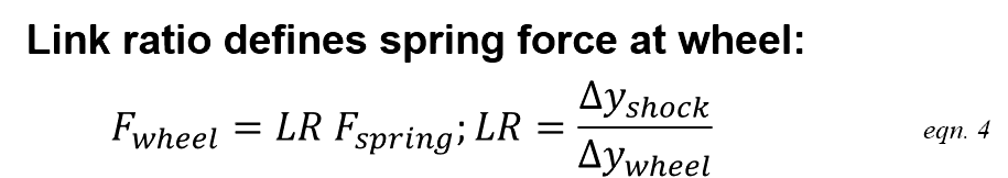
A simple teeter-totter torque balance defines force amplification through the link system. The suspension link ratio (LR) specifies how far the spring moves for an incremental change in wheel position, which also defines the teeter-totter force transfer through the suspension link to the rear wheel.
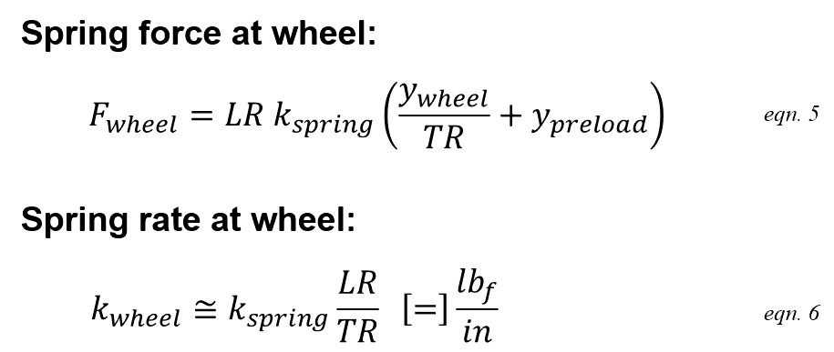
Combining the above gives a single equation specifying the spring force at the wheel for any given wheel position y.wheel.
Damping force at wheel
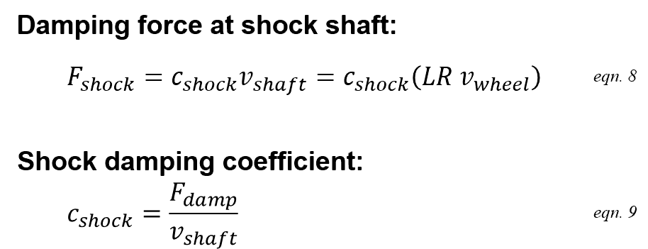
Link ratio (LR) defines the ratio of shock shaft velocity to wheel velocity.
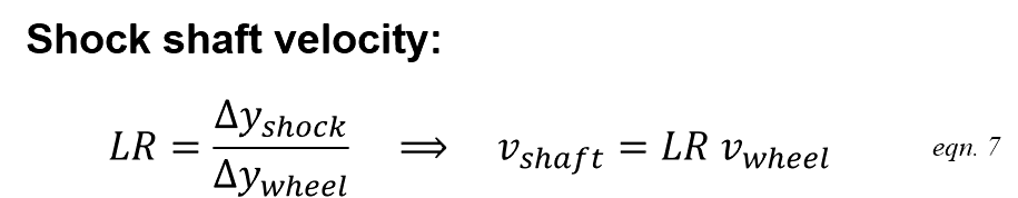
Damping force at the shock shaft is defined by the shock shaft velocity and damping coefficient. When combined with the above link ratio relationship the damping force at the shock shaft can be computed directly from the wheel velocity.
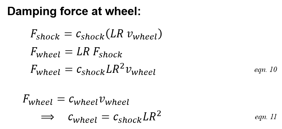
The same teeter-totter torque balance used for spring force defines the damping force transfer to the wheel. Combining the relationships gives a single equation defining damping force at the wheel given a specified suspension wheel velocity. The relationship also defines the shock damping coefficient at the rear wheel in terms of rear wheel bump velocity, c.wheel.
Link ratio spring force progression
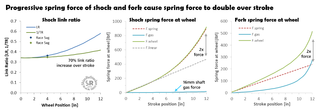
Linked suspension systems produce a progressive spring force increase through the stroke. Link ratios used in dirt bikes change from bike-to-bike and year-to-year but stay within a narrow range producing approximately a factor of two increase in spring force through the stroke.
The example below uses a typical MX link ratio demonstrating the spring force increase at the rear wheel. The shock gas force computed by Shim ReStackor has little effect on the overall spring force.
Fork spring force computed by Shim ReStackor includes the main spring, ICS system and gas spring force. Running stock oil levels shows the fork spring force also increases by approximately a factor of two over the stroke.
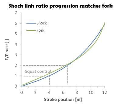
Normalizing the two curves with the spring force at race sag shows the spring force progression from the rear shock link ratio approximately matches the gas spring force progression of the fork. Matched spring force front and rear gives the suspension a balanced “feel” and is a principle factor in setting the rear shock link ratio.
Non-linked suspension systems use progressive shock springs to produce the same effect.
Linked suspension damping
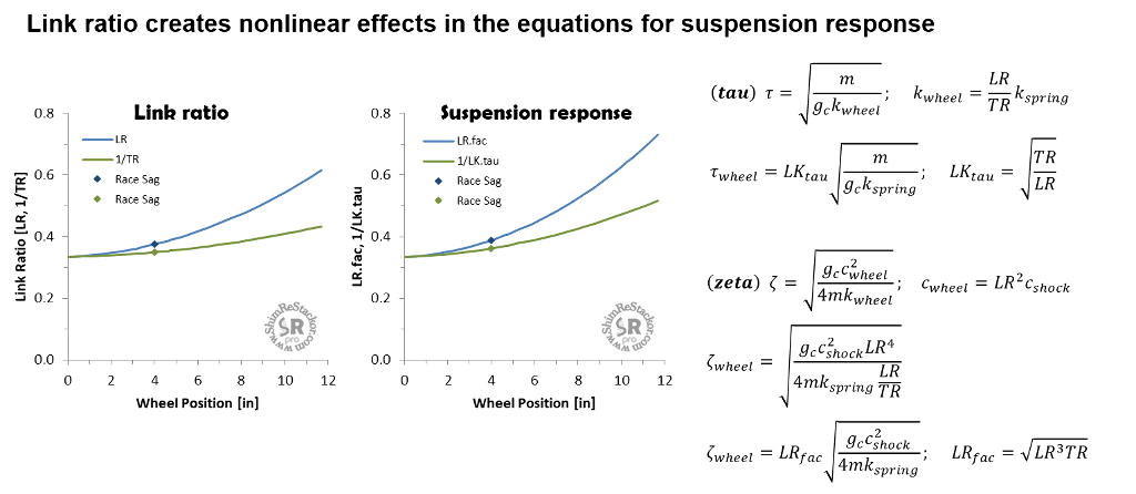
Spring-mass-damper theory defines the effect of spring rate and damping on suspension response for the special case of a constant spring rate and constant linear damping. Linked suspension systems make both of those terms nonlinear through the stroke.
Link ratio modifies the relationship for tau by the sqrt(TR/LR) which decreases with stroke depth. Tau defines the time required for the suspension to return to race sag and the decrease in tau with stroke depth simply states link ratio causes the spring force to increase deeper in the stroke shortening the time required for the suspension to return to race sag.
The equation for zeta is modified by LR.fac= sqrt(TR*LR^3). Zeta defines damping performance and the increase in the LR.fac term with stroke depth drives the suspension into an overdamped condition when pushed deeper in the stroke.
The change in link ratio through the stroke requires tuning the shock damping force curve to be compatible with the link ratio used in the suspension setup.
Ideal damping curve shape
Link ratio makes the damping force delivered at the wheel nonlinear and a function of stroke position. The fork gas force is also nonlinear making the spring force delivered at the wheel a function of suspension position. The impact of those two nonlinear terms on suspension response is defined by the spring-mass-damper zeta equation (more). By rearranging the zeta equation, the damping force curve shape needed to correct for nonlinear link ratio effects can be estimated.
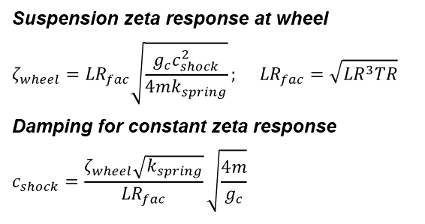
For a shock the link ratio LR.fac term increases with stroke depth. To compensate for the increase, and keep a constant value of zeta, the damping coefficient (c.shock) needs to drop off with stroke depth. Increased stroke depth implies higher suspension velocities meaning the ideal shock damping curve drops off at high speed. i.e. a digressive damping profile.
For a fork the LR.fac term is constant, but the k.spring term increases with stroke depth due to the gas spring force. To correct for the spring rate increase the shock damping coefficient needs to increase with stroke depth, i.e. a progressive damping force profile shown in the curves below.
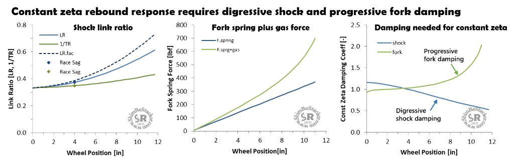
Shocks require a digressive rebound damping curve to compensate for link ratio. Forks require the opposite of a progressive damping curve to compensate for the increase in gas force.
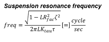
Link ratio also shifts the suspension natural resonance frequency from ideal spring-mass-damper theory due to the combined effect on spring rate and damping.
Linked suspension response
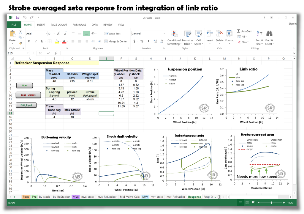
The nonlinear spring force from linked suspension systems and the nonlinear gas spring force from forks force the suspension to flip from under to overdamped conditions as the suspension moves through the stroke. Spring-mass-damper theory quantifies the instantaneous damping conditions but there is no simple algebraic relationship to integrate the nonlinear forces through the stroke and determine the overall suspension response.
Nonlinear spring and damping forces require numerical integration of the suspension stroke, stepping through the suspension stroke a microsecond at a time, evaluating the forces acting on the suspension, the resulting acceleration and stroke averaged suspension response.
Shim ReStackor response calculations perform that numerical integration and determine deep and shallow stroke suspension response accounting for the variation in nonlinear spring forces and damping occurring at the unique velocity of each stroke depth.
For the example screen shot below, the stroke averaged zeta coefficient drops off on shallow strokes. To fix the setup the shock needs to deliver more low speed rebound damping to deliver a constant suspension response zeta 0.7 value over the range of stroke depths.
Tuning damping force curves to deliver a consistent suspension response simply requires hacking around on the shim stack crossover position, thickness and diameter to deliver a constant zeta response coefficient over the range of suspension stroke depths (more).