Bleed systems provide a controlled leak path bypassing the shim stack controlled valve. Bleed allows free return of the suspension to race sag on low speed suspension motions.
Suspension “feel” heavily depends on the control of low speed bleed systems. Numerous bleed systems are used in shock absorbers.
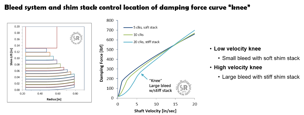
Damping curve knee
Clicker bleed circuits, leak jets, stack float or bleed shims all have a fixed constant area throat. Flow resistance through the throat is near zero at low speed and increases with velocity squared. The velocity squared pressure increase eventually produces enough backpressure to crack the shim stack open. Above the cracking pressure, digressive damping of the shim stack controlled valve controls the damping force curve shape.
The transition from velocity squared orifice damping to shim stack controlled digressive damping puts a “knee” in the damping force curve. The location of the “knee” is controlled by the bleed circuit flow area and stiffness of the shim stack.
Increasing the leak area provides more suspension compliance for rolling of trail trash. Decreasing the leak area provides more cornering “feel” and brake dive control.
Clicker bleed circuits
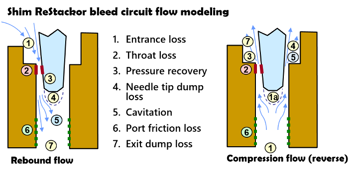
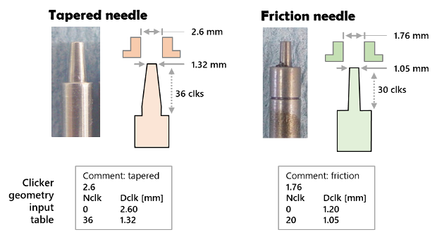
The clicker bleed circuit is basically a needle valve. Accurate damping force calculations require a clicker needle geometry table to describe the needle taper. The geometry table is a simple listing of needle diameter as a function of clicker position. Details are listed in the User Manual.
Seven types of flow losses occur in the clicker bleed circuits. Due to the geometry, flow losses are slightly different in the forward and reverse (rebound) direction. (more).
There are two basic styles of needles:
- Tapered needle: Screwing the needle in reduces the flow area
- Friction needle: Screwing the needle in increases the length of the high velocity throat increasing viscous friction losses
Low speed valve (LSV) shim stack
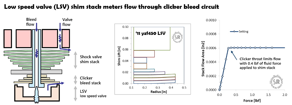
Low speed valve (LSV) refers to a shim stack on the clicker bleed circuit. Flow through the valve is small and limited by the clicker needle position. The LSV circuit is modeled in Shim ReStackor setting the valve port throat diameter (d.thrt) equal to the clicker needle flow area and modeling the shim stack in the usual way.
The example below computes the damping force for an ‘11 yzf450 fork base valve LSV circuit. With a fluid force of 0.4 lbf applied to the shim stack face the flow area through the LSV shim stack has deflected to the point where the clicker throat area limits the flow through the bleed circuit.
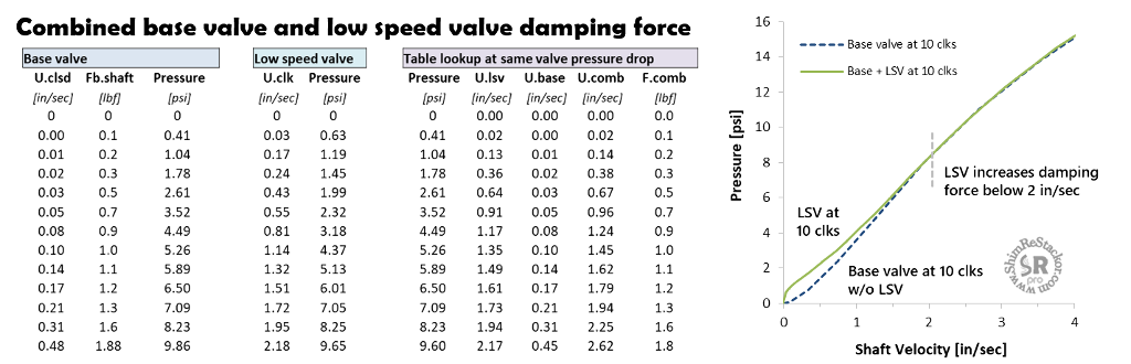
The LSV circuit creates two parallel fluid circuits through the fork base valve and LSV clicker circuit. Computing damping performance of the LSV circuit requires combining two separate Shim ReStackor calculations. The first calculation computes damping force through the base valve with the clickers closed. The second calculation computes damping force through the LSV circuit with the valve throat area set equal to the clicker throat area.
The two calculations are combined by selecting a sequence of progressively higher valve pressure drops and looking up the flow and shaft velocity through the base valve and the flow through the low speed valve at the same pressure drop. The total flow through the combined circuits is simply the sum of the two shaft velocities. At the selected valve pressure drop, the base valve damping force specifies the force on the shock shaft.
For the ‘11 yzf450 example, the LSV increases low speed damping by approximately 1 lbf up to shaft speeds of 2 in/sec. Above 2 in/sec the LSV shim stack has deflected to the point where the clicker throat limits the flow. Shim ReStackor calculations running the fork base valve only with clickers set at 10 out (dashed blue line) match the high speed LSV calculations since both are running the same bleed area.
Rebound separator valves on a shock operate in a similar fashion and primarily function as a check valve preventing reverse flow.
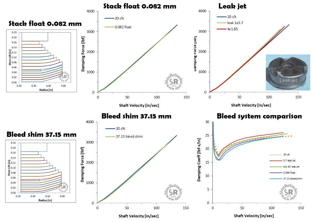
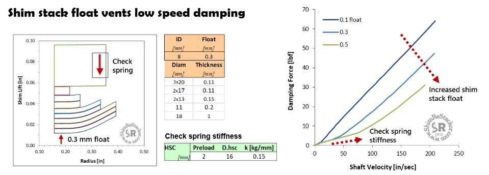
Stack float
Float allows the shim stack to physically lift off of the valve face to vent low speed damping. The rate of float opening is controlled by the HSC spring stiffness input and the cracking pressure controlled by spring preload.
The “Float” input specifies the float travel limit. Beyond that limit, the shim stack clamp hits a hard stop and damping force is controlled by the stiffness and deflection of the shim stack (more).
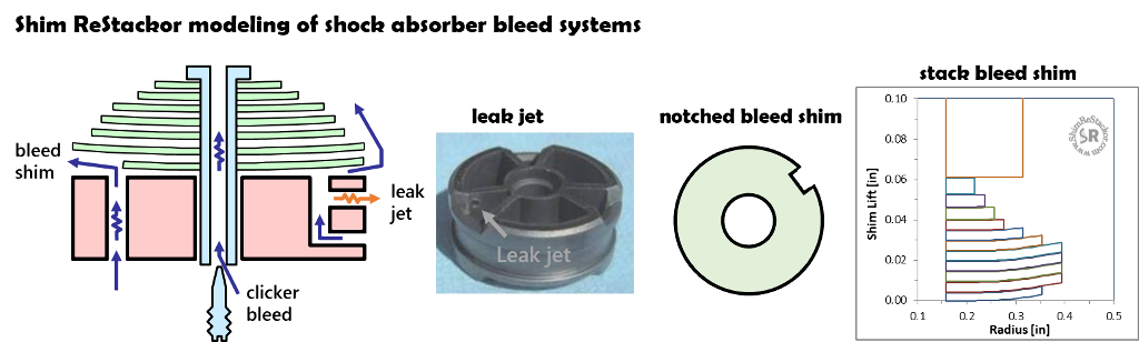
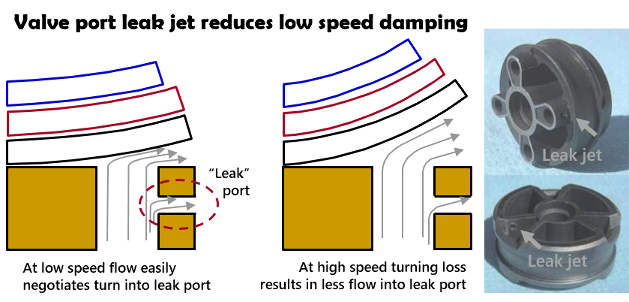
Leak jets
Leak jets are small holes drilled in the side of the valve port. Pressurized fluid in the valve port escapes through the leak jet venting low speed damping.
The 90 degree turn into the leak jet port reduces the flow effectiveness of leak jets at high speed.
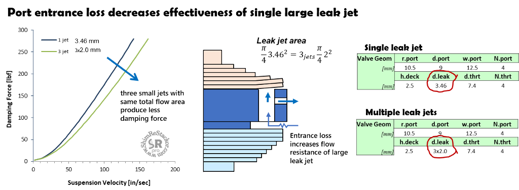
Multiple leak jets
A single 3.46 mm diameter leak jet has the same flow area as three 2.0 mm jets. However, 2.0 mm leak jets installed on three ports produces a more effective bleed.
The difference is caused by flow losses at the port entrance. A single 3.46 mm leak jet increases the fluid flow through that single port, which increases flow losses at the port entrance.
Spreading the leak jet across three ports increases the flow through each port by a small amount and since flow losses increase with velocity squared, the small increase in entrance flow loss spread across three ports is less than the large increase on a single port.
A central focus of the physics based models of Shim ReStackor is application of the fundamental physics of fluid dynamics to account for multiple flow losses occurring in the shock fluid circuits both in series and in parallel. Those flow losses make the flow “effectiveness” of a single leak jet, multiple leak jets, bleed shims or clicker bleed all slightly different.
Reliable modeling shifts the focus from endless testing to simply hacking around on the number and diameter of leak jets until the desired damping force curve is achieved.
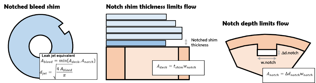
Notched bleed shims
Notched bleed shims provide a controlled leak at the valve face seat. The notch width, depth and shim thickness define the leak area.
The difference between the notch depth and valve seat diameter define the notch flow area (A.notch).
The notched shim thickness defines the dump flow area between the shim stack and valve deck (A.deck). The controlling bleed flow area is the minimum of the two.
Shim ReStackor models notched shims as a leak jet with the diameter defined by the minimum of A.notch or A.deck.
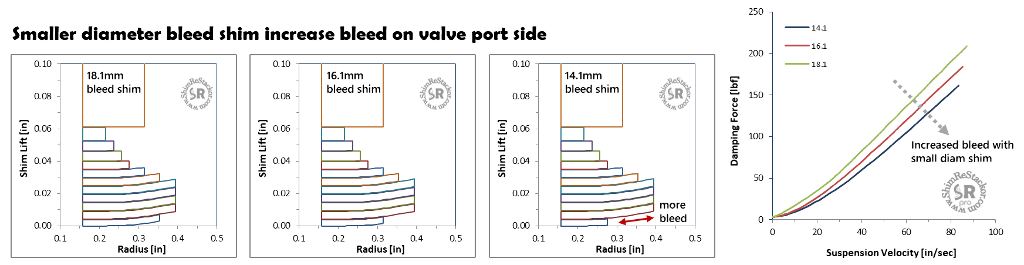
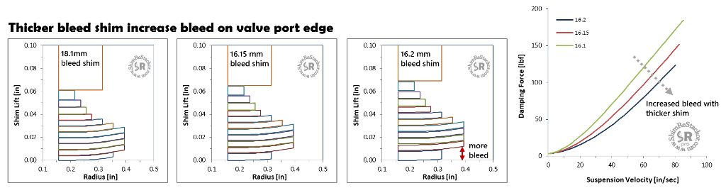
Bleed shim
Shim stack face bleed shims are smaller than the valve port seat diameter. The smaller diameter face shim forms an edge gap defined by the bleed shim diameter and thickness.
Decreasing the bleed shim diameter increases the gap length along the valve port side providing more bleed and softer damping.
Increasing the bleed shim thickness increases the gap height at the valve port edge.
Thicker bleed shim increase the gap, giving more bleed flow area and softer damping.
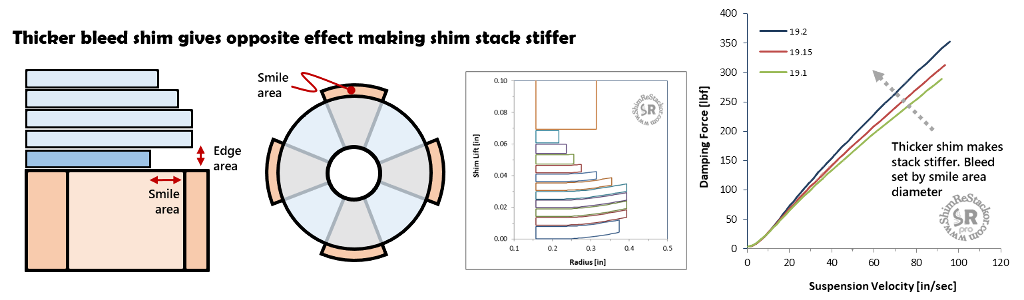
The example below shows the reverse effect where a thicker bleed shim increase damping force.
Bleed flow area is defined by two parameters: Edge flow area defined by shim thickness; Smile area defined by the shim and valve port diameter.
Smile area defines the bleed flow area for the large bleed shim diameter used in the example below. For that condition thicker shims make the shim stack stiffer and have no effect on bleed area.
Bleed system tuning
Notionally, 1.0 mm2 of bleed flow area through the clickers, leak jet, bleed shim, or stack float all produce the same effect. In detail, each circuit has a slightly different dependence on oil viscosity and density resulting in different bleed flow rates as the area is changed.
While those differences are real, they have little effect on tuning. For tuning, bleed circuits are simply modified - increasing or decreasing flow area - until the desired bleed effect is achieved.
That shifts the focus from trying to guess the bleed flow rate and range of shaft velocities influenced by bleed to computing the actual flow using Shim ReStackor. Tuning the shim stack and bleed circuits together as a system gives detailed fine tuning control of the shape of the damping force curve.
“Shim ReStackor: Fine tune your suspension setup far beyond the limits previously possible”