
A wheel rolling over a square edge bump forces the hub to follow an arc path. With the simplifying assumption of a ridged wheel the hub arc path defines the suspension bump velocity.
The bump velocity is highest at bump impact where the arc path is steep. The bump velocity asymptotically rolls off as the wheel approaches the top of the bump.
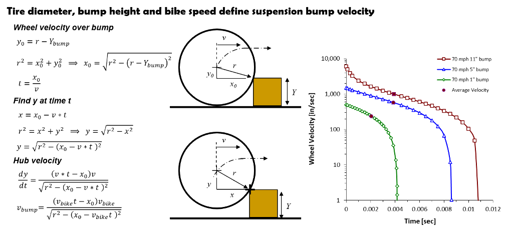
Bump velocities are highest at bump impact
Tire compliance
A more conservative estimate assumes the tire has perfect compliance and the sidewall collapses on bump impact. With the tire collapsed, the rim diameter defines the hub arc path and the suspension bump velocity.
Tire compliance reduces the peak suspension velocity at bump impact and produces suspension velocities similar to the simplified bump averaged suspension velocities defined below.
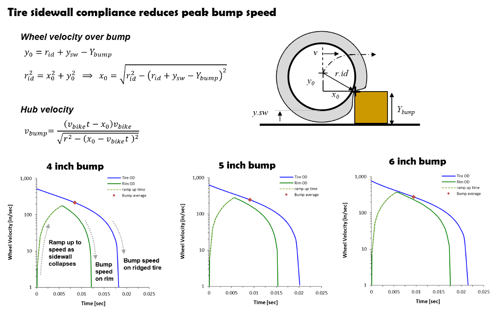
Tire compliance reduces initial suspension velocity at bump impact
Bump average velocity
The simplest approach to estimating bump velocity simply divides the bump height by the time required for the wheel to roll to the top of the bump giving the average suspension vertical bump velocity.
The distance traveled from the point of bump contact to the top of the bump is L.b. The time required for the bike to move that distance is t.bump = L.b/v.bike.
Over that time, the wheel has to move vertically by the bump height (y.bump) or the rim ends up with a flat spot. Bump height divided by time defines the suspension average vertical bump velocity (y.bump/t.bump).
The bump average velocity is easy to estimate and in the ballpark of the more sophisticated methods defined above.
Since test rides evaluate suspensions in generalities like too soft or too stiff on notional “eye-balled” bump heights. The simplified bump averaged suspension velocities are close enough to estimate suspension speeds for shock tuning.
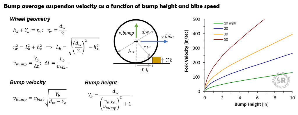
Bump average velocity closely matches tire compliance peak velocity and is the preferred approach for estimating suspension bump velocities
Example bump velocity calculation
A 21 inch dirt knobby hitting a four inch bump at 50 mph produces a wheel bump speed of 359 in/sec.
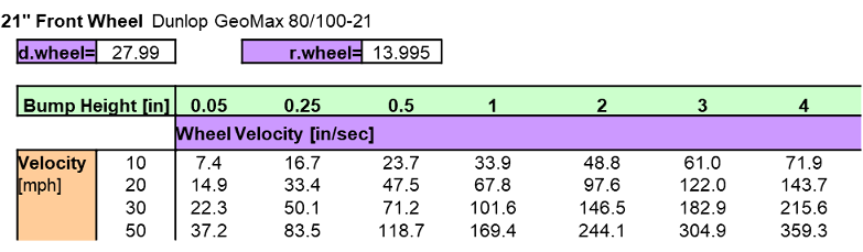
21 inch front wheel bump average velocity
An 18 inch rear wheel knobby hitting the same bump at the same 50 mph speed produces a slightly higher bump velocity of 368 in/sec due to the smaller tire diameter.
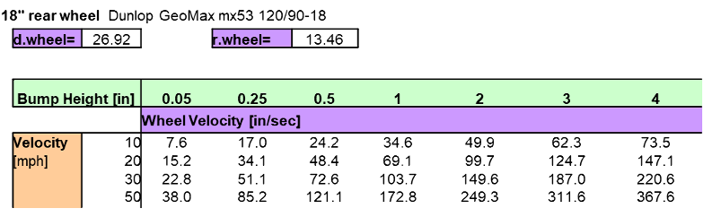
18 inch rear wheel bump average velocity
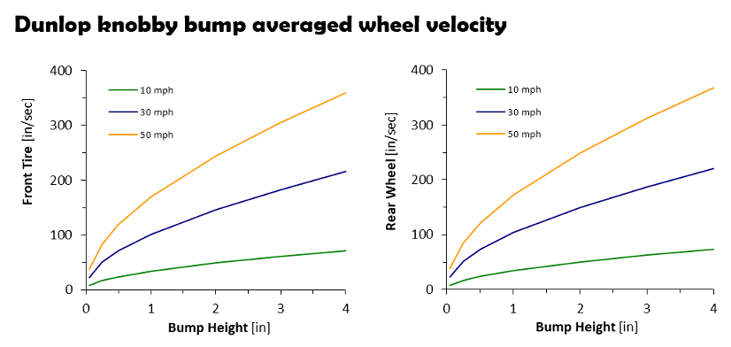
Dirt knobby suspension bump velocity
Optimum fork bump angle
On bump impact, the contact point on the tire or rim transmits a force to the wheel hub. The angle of the transmitted force depends on the tire diameter and bump height.
If the bump force angle lines up with the fork rake angle the fork will smoothly move through the stroke. If the force angle is misaligned, the bump force puts a side load on the fork bushings increasing the sliding friction and reducing fork compliance.
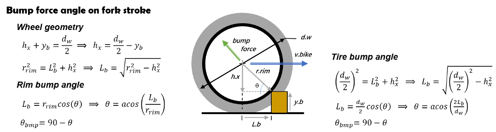
Bump height and wheel diameter define force angle transmitted to suspension
Bump heights of 1.5 to 4 inches produce a bump force angle that lines up with the rake of a 27 degree fork. Larger bumps in the four inch range are assumed to flatten the tire sidewall with the rim diameter defining the bump force angle.
If the bump is sinusoidal shaped, instead of square edged, the wheel contact point is roughly mid-bump. That doubles the force aligned bump height to bump heights of 3 to 8 inches.
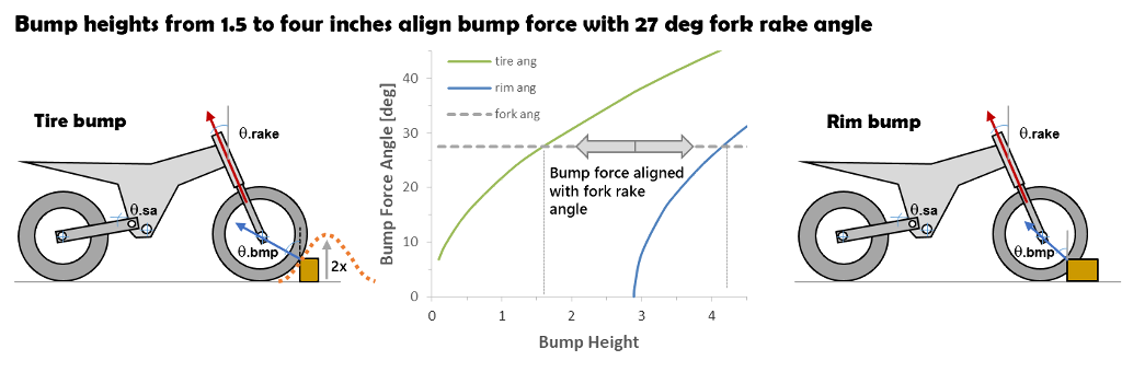
Bump force transmitted through wheel hub lines up with fork rake angle for bump heights of 1.5 to 4 inches
Gravity dictates jump landing impact velocities. A three foot freefall produces an impact velocity of 152 in/sec which gives a direct method to estimate impact velocities on MX jump landings.
Shim ReStackor suspension response calculations compute the capability of the suspension to absorb jump landings using inputs of spring rate, link ratio, gas force and compression damping.
Tuning suspensions to absorb a three foot jump landing simply requires hacking around on the shock absorber compression shim stacks to absorb the 152 in/sec impact velocity or any other jump height of interest (more).
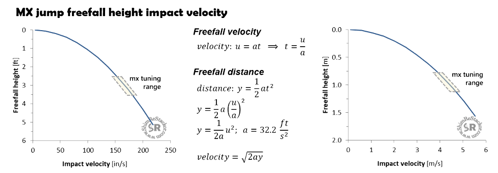
Jump landing impact velocities are dictated by gravity
Compression damping tuning compromise
A three foot jump landing freefall and a 2.5 inch bump hit at 30 mph produce the same suspension velocity. Compression damping stiff enough to absorb the bike plus rider weight on jump landings will cause the chassis to deflect off a 2.5 inch bump hit at 30 mph. Both events produce the same suspension velocity.
To make hill climbs with roots, rocks and steps enduro suspensions need soft compression damping to generate the suspension compliance and wheel ground contact necessary to complete hill climbs.
MX setups need stiff compression damping to avoid bottoming on jump landings. The stiff compression damping needed to land a three foot jump freefall will cause the chassis to deflect off a 2.5 inch bump hit at 30 mph.
Ground compliance versus jump landing bottoming resistance defines the difference between MX and enduro suspension setups. The suspension cannot do both at the same stroke velocity (more).
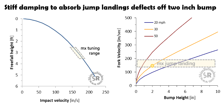
Three foot jump freefalls and 2.5 inch bumps produce the same suspension velocity forcing suspension setups to either focus on jump landing bottoming resistance or bump compliance