
The specific damping force tuning targets needed for a baseline suspension setup are specified by suspension tuning "rules of thumb". Collectively, those rules also define what a “good” damping force curve “looks-like” with specific low, mid and high speed damping targets.
Baseline damping targets:
- Rebound damping: zeta= 0.707 across the stroke depth range
- High speed compression: Peak compression damping force on wheel bottoming stroke matches peak spring force. Matched peak force gives the stroke a consistent “feel”
- Mid-speed compression: Matched rebound/compression damping force requires damping ratios of:
- Fork: r/c= 3.0 to 3.5:1
- Shock: r/c= 2.0 to 2.5:1
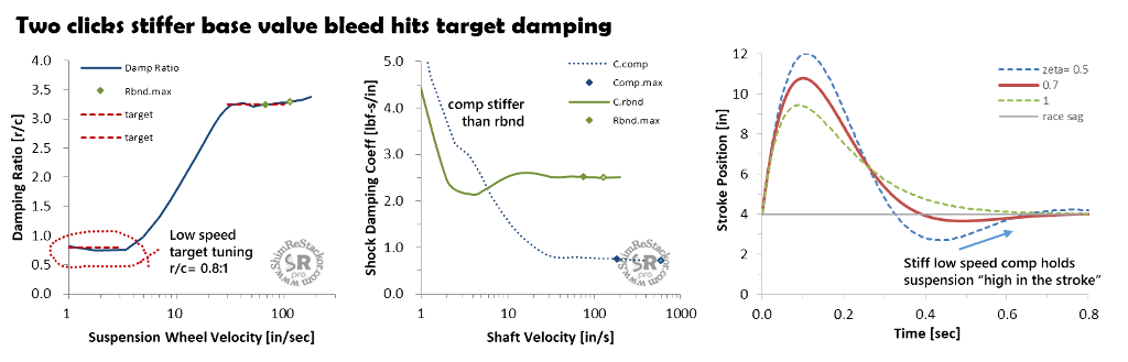
- Low speed compression: Damping ratio of 0.8:1 below wheel speeds of 6 in/sec
- Catches rebound overshoot and holds suspension “high in the stroke”
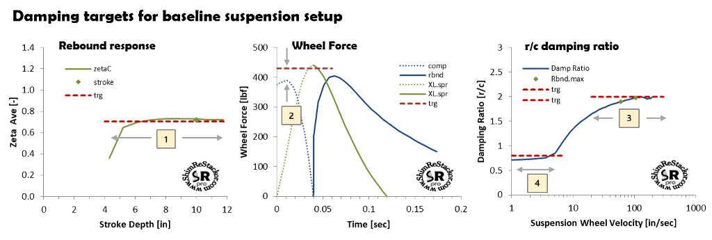
Shim ReStackor response calculations provide specific damping targets for a baseline suspension setup
Rebound damping
Riders have an uncanny ability to twirl clickers and hit rebound damping at zeta values of 0.7. The reason is simple. Rebound damping stiffer than zeta 0.7 gives slow response causing rebound to pack. Softer damping below zeta 0.7 allows the suspension to baby-buggy after a bump giving poor suspension “feel”.
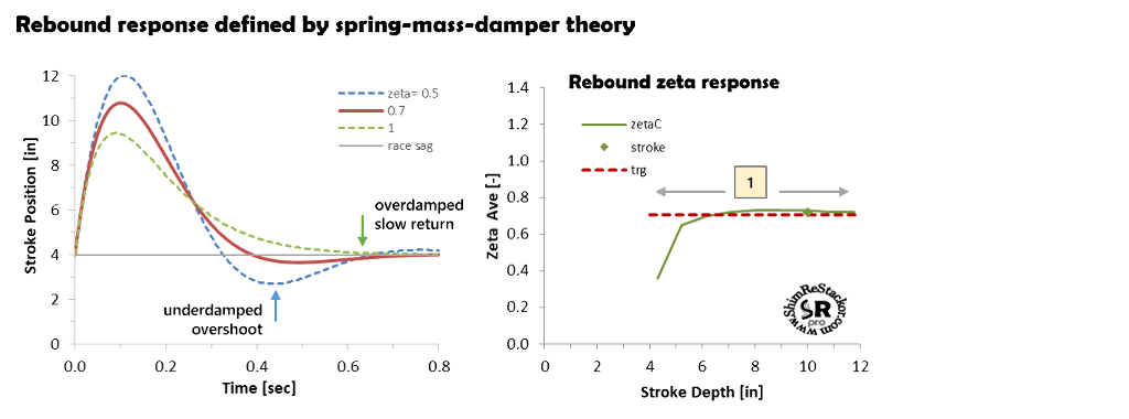
Spring-mass-damper theory defines zeta values of 0.707 to give the fastest possible rebound response with damping stiff enough to suppress suspension resonance. That fact from spring-mass-damper theory sets the baseline rebound damping target at zeta values of 0.7.
Suspension response from spring-mass-damper theory shows why zeta values of 0.7 are preferred. Zeta values of 0.7 slightly overshoot race-sag on rebound. Stiffer damping at zeta of 1.0 prevents overshoot, but takes longer to return to race-sag causing rebound to pack.
Lower values of zeta 0.5 overshoot race-sag by two inches producing a large baby-buggy motions and poor suspension “feel”. Zeta values of 0.7 get back to race sag fast, minimize overshoot and provide damping stiff enough to suppress resonance motions.
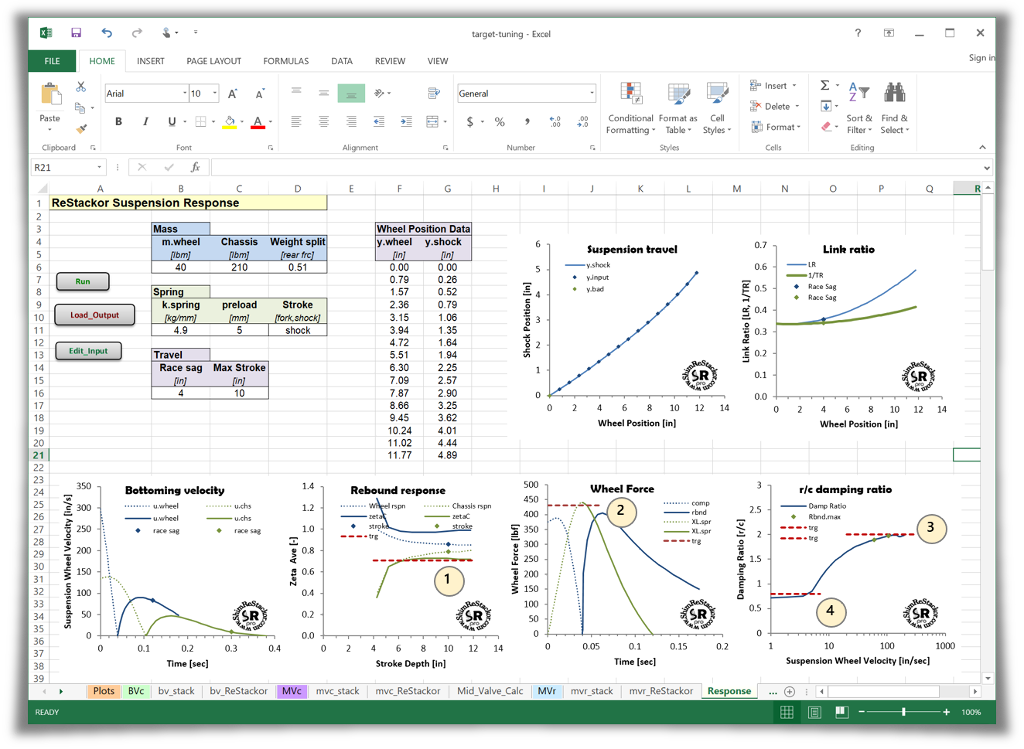
Shim ReStackor suspension response calculations compute the instantaneous zeta value and integrate response over the stroke to determine the stroke averaged zeta response correcting for link ratio effects.
Tuning to the target 0.707 zeta value simple requires hacking around on the rebound shim stack, adding or removing shims, to hit the target zeta value with a flat curve giving consistent response across the range of suspension stroke depths.
Spring-mass-damper theory defines the time required for the suspension to return to race sag
Rebound tuning example
The example illustrates a typical suspension tuning problem. The rider has twirled clickers around to get good rebound response for small strokes around race sag.
But, when pushed deeper in the stroke the suspension goes underdamped.
Fast rebound on deep strokes causes the suspension to “kick” in the whoops and on jump landings.
To fix the setup, the shock needs stiffer high speed rebound damping and more bleed at low speed to keep the zeta constant across the stroke depth range.
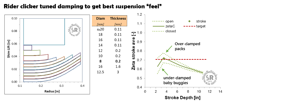
Clicker tuning gives the right zeta value at low speed, but deep strokes are underdamped causing the suspension to kick in the whoops
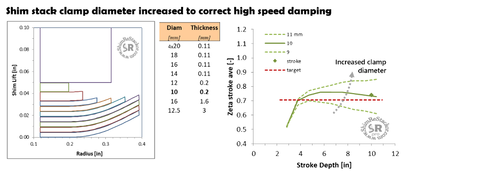
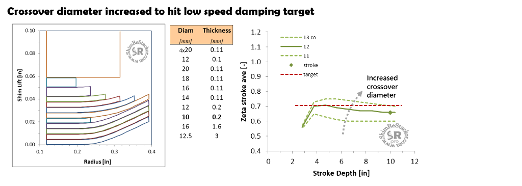
A larger 10 mm stack clamp increases high speed damping and hits the damping target on a ten inch stroke. But mid-speed rebound damping is too stiff.
The shim stack needs a crossover to reduce mid-speed damping and flatten the zeta curve across the range of stroke depths.
Adding a 12 mm crossover behind the face shims hits the target zeta= 0.7 value at mid-speed. But, adding the crossover gap softens high speed slightly.
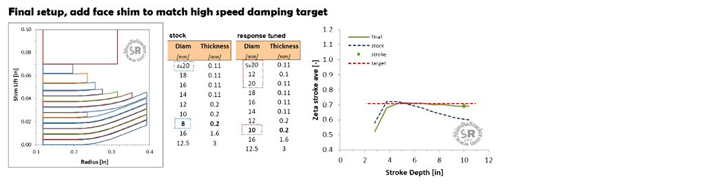
The shim stack needs a couple of additional face shims to stiffen high speed damping.
Adding an additional face shim stiffens high speed and produces a near flat zeta curve across the range of suspension stroke depths.
A flat curve with a constant value of zeta produces consistent suspension response, “feel” and behavior across the range of suspension stroke depths.
The capability to “see” the damping force effect of each shim stack modification across the range of stroke depths and suspension velocities makes tuning simple, easy and intuitive. Each modification can be fine-tuned individually or in combination to get the desired damping force curve shape.
The example required: two additional face shims; a crossover; and a stiffer stack clamp. Individually, each modifications was insufficient. Correcting the damping force curve shape required multiple simultaneous changes.
Figuring out the combination of modifications needed is nearly impossible using the “one thing at a time” seat of the pants tuning approach. Shim ReStackor makes it easy.
Bottoming velocity
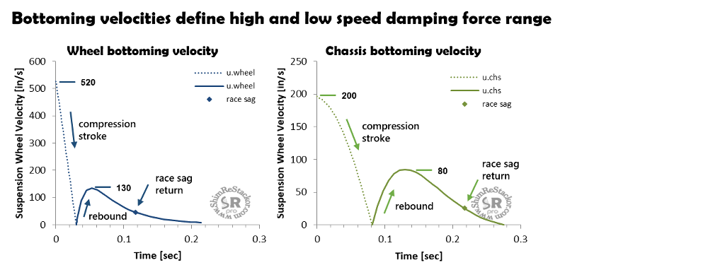
Response calculations compute the bump velocity that bottoms the wheels and the jump landing impact velocity that bottoms the chassis. Wheel bottoming defines the shocks maximum shaft velocity and the high speed shaft limit for tuning. Jump landing chassis bottoming defines the shocks low speed damping force range.
Bottoming velocities are evaluated at 80 to 85% of max travel. The final 15% to 20% of suspension travel hits the bump rubber or bottoming cones on a fork. At that point, the bottoming system controls suspension motion, not the shock.
Knowing the suspension velocity that bottoms the wheels and jump landing impact velocity that bottom the chassis allows the damping force curve to be tailored to meet the specific needs of the rider.
High speed compression damping
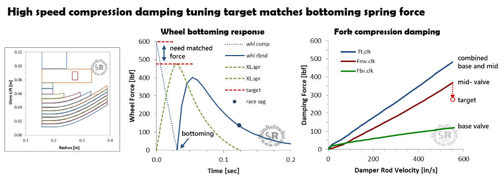
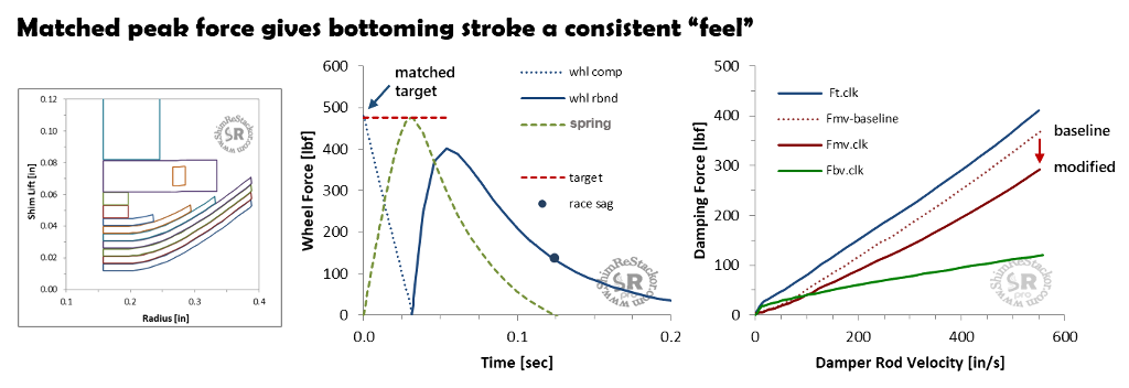
The high speed compression damping target sets the peak compression damping force on the wheel bottoming stroke to match the peak spring force. Matched peak force keeps the overall force through the stroke approximately constant with compression damping dropping off as the spring force ramps up.
Constant force gives the wheel bottoming stroke a consistent “feel” and absorbs the maximum bump energy.
For the example above, wheel bottoming occurs at a bump impact velocity of 520 in/sec producing a peak compression damping force near 600 lbf.
As the suspension slows through the stroke, compression damping drops-off to zero at bottoming where the spring force peaks at a maximum force of 480 lbf.
The peak compression damping force at bump impact is 120 lbf higher than the peak spring force at bottoming. The 120 lbf higher force at bump impact makes the suspension harsh.
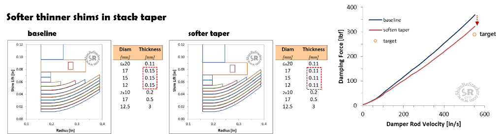
To hit the target of matched peak force compression damping needs to be reduced by 120 lbf at bump impact. For this fork example, the mid-valve compression stack will be softened to hit the bump impact damping target.
Reducing the thickness of the shim stack taper shims from 0.15 mm to 0.011 mm reduces the peak compression damping force by approximately 50 lbf.
To hit the matched peak force target high speed compression damping needs to be further reduced.
Removing two face shims softens compression damping and hits the target damping force.
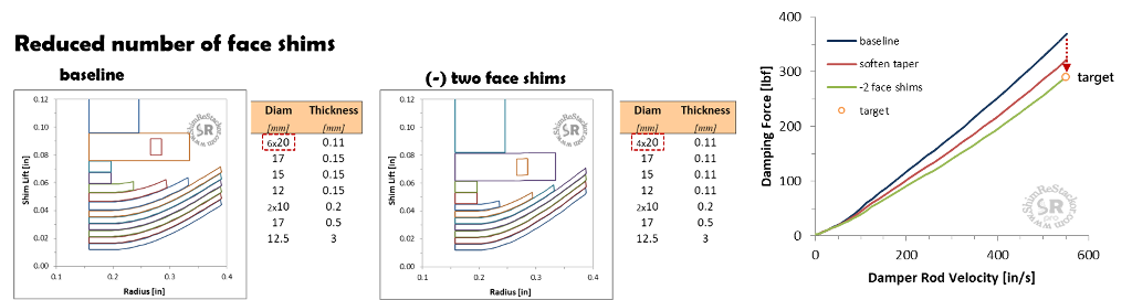
Hitting the target compression damping required softening the shim stack taper and removing two face shims.
With softer compression damping the wheel bottoming velocity is reduced to 500 in/sec compared to the original value of 550 in/sec.
If test rides show wheel bottoming is a problem the setup needs stiffer springs and stiffer compression damping to keep the matched peak force criteria and increase the suspension bottoming velocity.
There are numerous options for tuning compression damping: Increased stack float, softer stack taper, smaller clamp, thinner shims or reduced number of face shims.
Each of those options are easy to evaluate in Shim ReStackor allowing the best combination of modifications to be selected.
Chassis bottoming
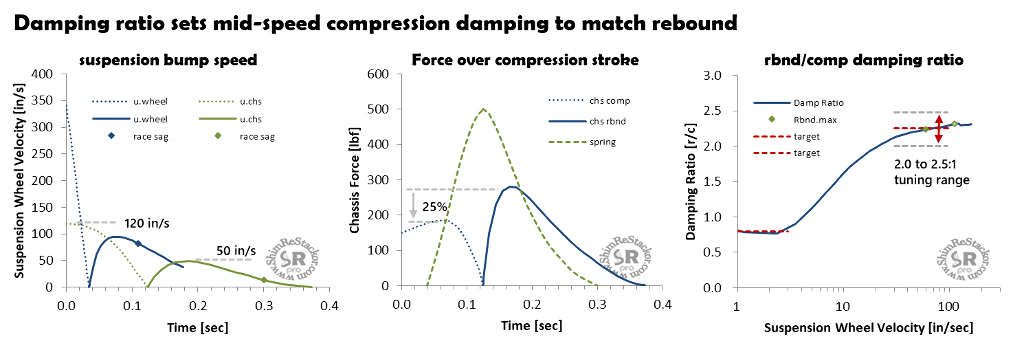
Shim ReStackor calculations determine the chassis bottoming velocity by dropping the vehicle from progressively higher heights to determine the impact velocity that drives the suspension to the specified “Max stroke” depth. Bottoming in normally evaluated at 80 to 85% of full travel where the stroke hits the bump rubber or bottoming cones. The example below bottoms the chassis at an impact velocity of 120 in/sec. The peak rebound speed on return from bottoming is approximately 50 in/sec.
Chassis compression damping
To give the suspension stroke a balanced and symmetric “feel” compression damping is tuned by the ratio of rebound/compression damping. Suspension bump speeds in compression are approximately double the velocities in rebound. The velocity difference makes the damping force in compression approximately equal to the damping force in rebound when the rebound/compression damping ratio is 2:1. Equal force gives the suspension a symmetric “feel”.
The baseline target for a shock has a damping ratio range from 2.0 to 2.5:1. The range allows shock tuning to rider preference. The example below tunes chassis compression damping to deliver a rebound/compression damping ratio of 2.25:1. The 2.25:1 ratio produces a peak compression damping force that is approximately 25% below the peak rebound force. Softer compression damping gives a “plusher” ride at bump impact.
Forks run lower values of race sag at approximately 20% of travel. Less race sag gives forks more bump travel, which requires higher bump speeds to bottom the suspension. Due to the higher bump speed producing higher compression damping forces the target for matched force is a rebound/compression damping ratio of 3.0 to 3.5:1 for a fork.
Alternative compression damping targets
The damping ratio targets used for the baseline setup attempt to match the bump energy dissipated in compression with the bump energy dissipated in rebound to give the suspension stroke a symmetric “feel”.
Other approaches set the peak compression damping force to match the peak spring force to maximize the suspension bump compliance, or set stiffer compression damping with the single goal of providing jump landing bottoming resistance (more).
Chassis tuning example
To establish the compression damping target, rebound damping must be set first. The example uses the rebound setup tuned above to deliver zeta values of 0.7 and sets compression damping to deliver a 2.25:1 damping ratio.
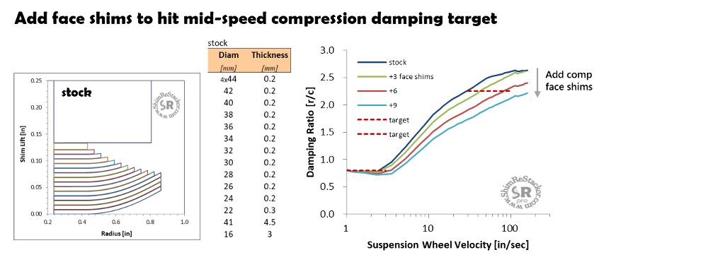
Running Shim ReStackor on the stock compression damping setup gives a rebound/compression damping ratio that overshoots the target 2.25:1 damping ratio. To high the target, stiffer compression damping is needed.
Adding face shims stiffens compression damping moving the damping ratio toward the target value. However, the addition of face shims does not fix the curve shape. The curve is too stiff at low speed (around 20 in/sec) and too soft at high speed above 100 in/sec. That produces a suspension setup that is initially stiff but then blows through.
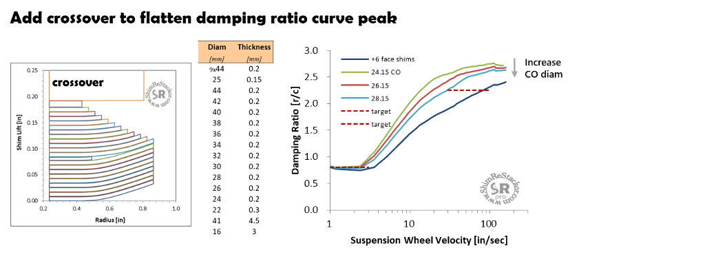
Fixing the setup requires changing the compression damping curve shape to deliver softer damping at low speed and stiffer damping at high speed. The shim stack needs a crossover.
Adding a crossover softens low speed and stiffens high speed after the crossover closes. That combination flattens the damping ratio curve over the 20 to 100 in/sec range.
However, the crossover gap softened compression damping. While the curve is flat, the damping ratio has increased into the 2.75:1 range. Hitting the target requires a stiffer high speed stack.
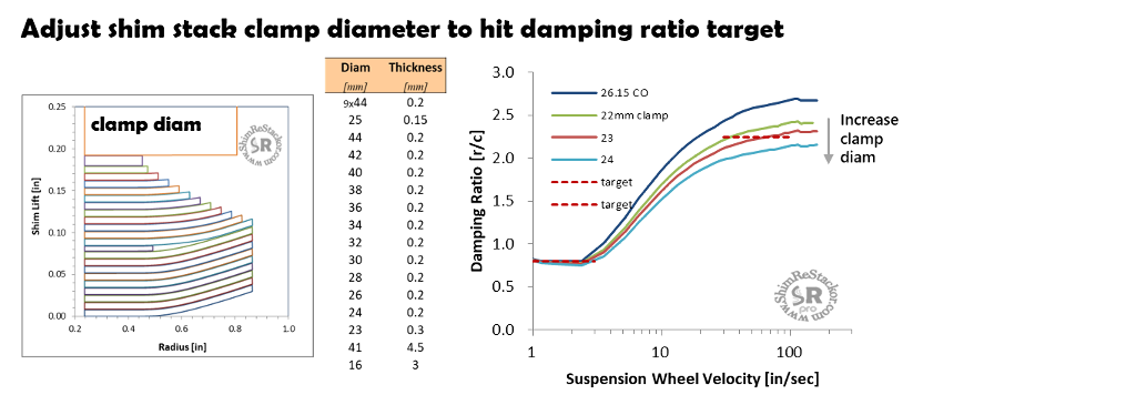
Progressively increasing the clamp diameter shows a 23 mm clamp comes closest to hitting the target damping ratio.
With the larger clamp the damping force at 20 in/sec is a little low. Some additional fine tuning is needed.
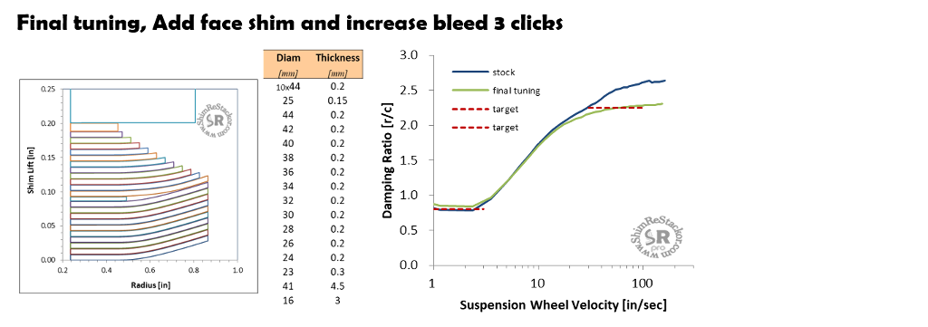
For the final tuning an additional face shim was added and the clickers opened by three clicks to obtain the best match to the target damping ratio.
There is no secret formula to determine the exact shim stack modifications needed to achieve a specific damping force curve shape. Tuning is simply done through hacking.
Fixing the setup required the addition of face shims, a shim stack crossover and retuning the stack clamp diameter. Those modifications are easy to evaluate in software, allowing each modification to be fine-tuned to produce the best fit. Experimenting with different combinations of shim stack modifications to figure out the best configuration can easily require 30 to 40 tests.
Thirty tests on a dyno at $50/stroke works out to $1,500, which defines the difference between close enough and perfecting the damping force curve.
Fine tuning shim stacks in Shim ReStackor where you can “see” what the shim stack is doing and the effect of each modification on the shape of the damping force curve makes tuning simple, easy and intuitive. Rapid calculations allow fine tuning of each feature to obtain the best damping force curve shape.
Low speed compression damping
Rebound damping at zeta values of 0.70 is underdamped. Underdamped means the rebound stroke will overshoot race sag and baby-buggy back. Baby-buggy motions give the suspension poor “feel”.
Tuners have a trick to suppress the low speed baby-buggy motions.
When rebound overshoots race-sag, low speed compression damping “catches” the rebound overshoot, holds the suspension “high in the stroke” and heavily damps the return stroke to race-sag to suppress further baby-buggy motions.
The low speed compression damping target is a rebound/compression damping ratio 0.8:1 at suspension speeds below 6 in/sec. With rebound tuned to zeta values of 0.7 the target damping ratio produces a compression damping zeta value of 0.875. The near critical damping heavily damps the return stroke, which prevents baby-buggy motions.
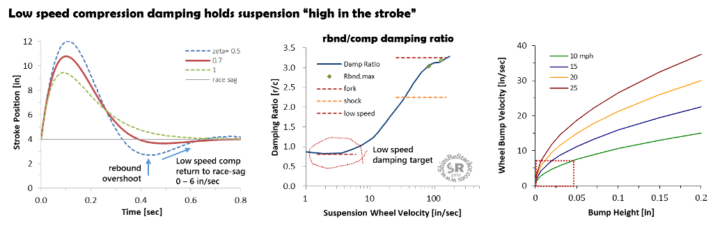
Stiff low speed compression damping at 6 in/sec has no impact on bump compliance or harshness.
Bump heights of 1/32” hit at 10 mph produces a suspension velocity of 6 in/sec . Bump that small are completely consumed by tire compliance and have not influence on ride harshness.
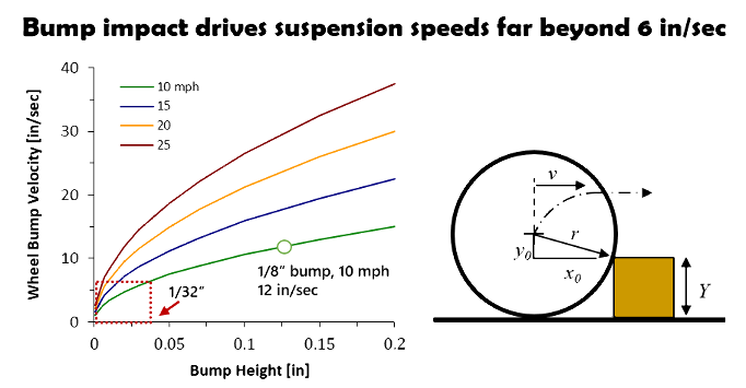
Larger bumps in the ¼ inch range hit at 20 mph drive compression speeds above 30 in/sec. Tuning low speed compression damping to blow-off above 6 in/sec gives the needed compliance on ¼ inch bumps.
Ultra-low speed suspension motions in the 0-6 in/sec range only occur when the chassis is drifting back to race sag. Heavily damping the race sag return stroke holds the suspension “high in the stroke” and prevents race-sag baby-buggy motions.
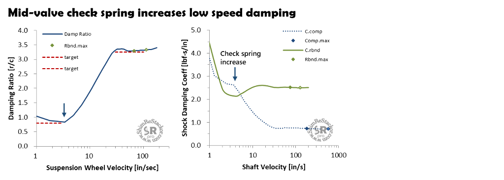
Low speed compression tuning
Low speed compression damping can be tuned using the clicker bleed circuits; Oil viscosity; Stiffness of the base valve shim stack; Low speed valve (LSV) clicker bleed stack or rebound separator valve in a shock.
The example below uses the mid-valve check spring to control low speed compression damping.
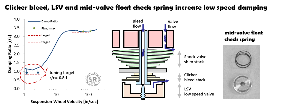
Float check spring
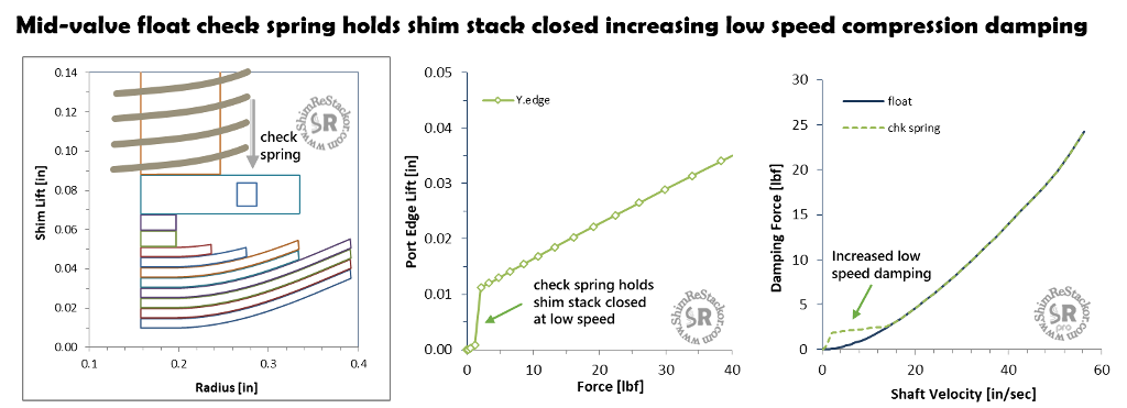
The mid-valve check spring holds the shim stack float closed at low speed forcing all flow through the mid-valve bleed circuits. Tuning the check spring stiffness and preload sets the shim stack cracking pressure and the stiffness of compression damping at ultra-low suspension speeds.
The stiffness of check springs varies from 0.02 to 0.6 kg/mm providing a wide range of tuning options.
The example below uses a 0.2 kg/mm check spring with 5 mm of preload to hold the shim stack closed at low speed. A force of 2.2 lbf on the shim stack face cracks the shim stack open and 2.3 lbf opens the stack to the 0.25 mm float limit providing a rapid transition from stiff low speed damping to the lighter damping needed for small bump compliance.
Closing the base valve clickers by two clicks gives the needed low-speed damping force increase hitting the target 0.8:1 damping ratio.
Tuning the check spring preload gives the needed low speed compression damping at 3 in/sec.
To hit the target at 1 in/sec the fork base valve bleed circuit needs modification.
Baseline suspension setup
Suspension tuning “rules of thumb” specify four damping targets needed to get to a “good” baseline suspension setup:
- Rebound damping: zeta= 0.707 across the stroke depth range
- Zeta values stiffer than 0.707 cause the suspension to pack
- Zeta values less than 0.707 are insufficient to suppress suspension resonance motions
- High speed compression: Compression damping matches peak spring force on wheel bottoming stroke
- Constant force through stroke gives bottoming stroke a consistent "feel"
- Mid-speed compression: Rebound/compression damping ratios set to give suspension a consistent "feel" with equal bump energy dissipatio nin compression and rebound
- Fork: r/c= 3.0 to 3.5:1
- Shock: r/c= 2.0 to 2.5:1
- Low speed compression: Damping ratio of 0.8:1 below wheel speeds of 6 in/sec
- Catches rebound overshoot and holds suspension “high in the stroke”
Shim ReStackor response calculatios provide specific damping targets for a baseline suspension setup
If the baseline setup rides too stiff you need a softer spring. If the suspension bottoms you need a stiffer spring. In either case, damping is tuned to the spring rate used.
The baseline provides a starting point with balanced compression and rebound damping. The suspension can be fine tuned from there and compression damping adjusted to control jump landing bottoming.