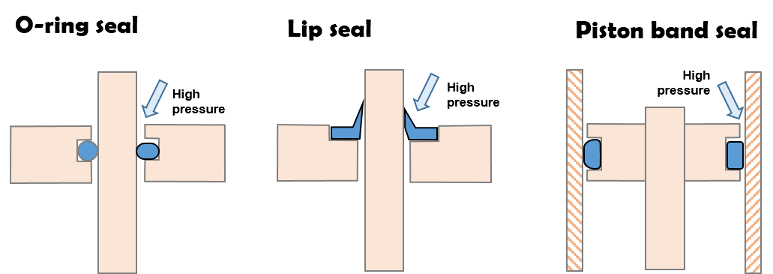
Both O-rings and lip seals are used in shock absorbers. Both seal types are “pressure activated” meaning the sealing force increases as pressure is applied to the seal.
Pressure activated also means the seal drag force increases as pressure is applied to the seal.
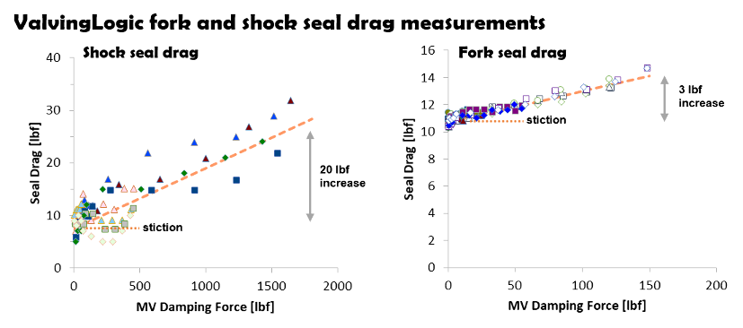
Seal drag data
ValvingLogic has measured seal drag of KYB, Showa and WP shocks under both static and high speed conditions. Shock seal drag increases by 20 lbf at high speed while fork seal drag increases by approximately 3 lbf.
Shim ReStackor damping force calculations include seal drag and the seal drag increase as the shock is pushed to progressively higher pressures at high speed.
There are two components to seal drag:
- Static stiction
- Pressure activated drag
Static stiction causes low speed suspension motions to lockup, preventing the suspension from freely returning to race sag creating poor suspension compliance over small bumps.
Pressure activated drag increases the damping force at high speed due to the increased internal pressure acting on the seal.
Shim ReStackor damping force calculations compute both types of drag and correct for pressure changes due to modification of the shim stack configuration.
Seal drag measurement
Setting race sag gives a direct measurement of seal drag stiction. Lifting the bike slightly and allowing the suspension to settle back to race sag; or pushing the bike down and allowing the suspension to rise to race sag quantifies stiction by the stroke height difference.
The race sag position difference coupled with the suspension spring rate and link ratio quantifies the seal drag stiction force.
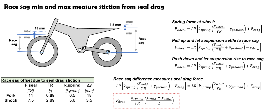
Eleven pounds of fork seal drag produces a race sag difference of 18 mm (+/- 9 mm). Shock seal drag produces a race sag difference of 3.5 mm.
Stiction measurements outside that range indicate the forks may not be aligned, the linkage system needs greasing or the shock has a poorly installed seal causing high drag.
Dyno damping force measurement
Shock absorber damping force measurements are composed of two elements: hydraulic damping from the shock circuits and drag from the shock seals. Dyno tests typically subtract the zero velocity seal stiction from the measured shaft force to highlight the hydraulic damping force produced by the shock.
However, the static stiction dyno correction does not account for pressure activated seals which increase the seal drag by 20 lbf when operated at high pressure as shown by the above ValvingLogic data. That creates a 20 lbf difference between the true hydraulic damping force of the shock and the combined damping plus seal drag measured in dyno testing.
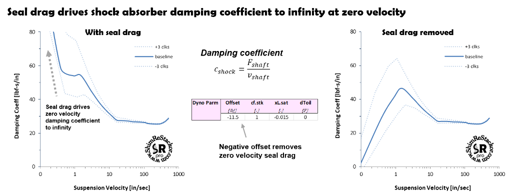
Shock damping coefficient
Seal drag dominates the low speed damping force and suspension response for small motions around race sag. Shim ReStackor damping force calculations include seal drag for that reason. The effect of seal drag on low speed damping is easily seen in plots of the shock absorber damping coefficient. As shaft velocities approach zero the damping coefficient goes to infinity due to the definition of damping coefficients as damping force/shaft velocity.
The seal drag force can be removed from Shim ReStackor calculations using the “Offset” input parameter. The Offset input is added to the computed damping force.
Adding a negative offset adjusts the computed damping force to produce zero damping force at zero shaft velocity. This is the same process dyno tests use to correct the measured damping force for seal drag. However, the correction does not correct for dynamic seal drag as mentions above.