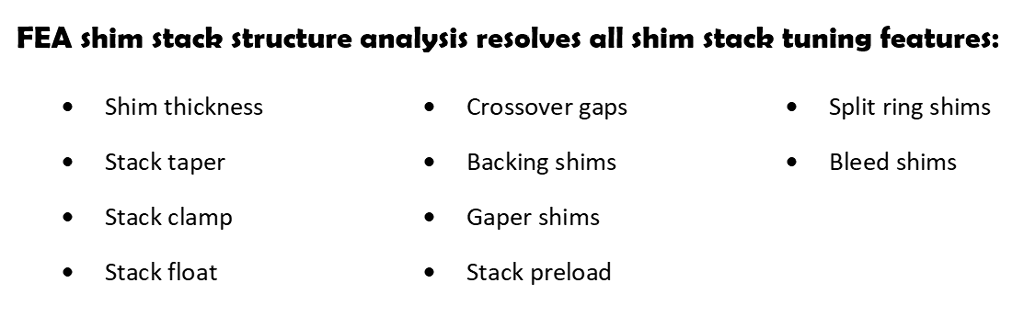
Shim stack stiffness
The stiffness of complex shim stack structures cannot be estimated by a simple sum of shim factor shim stiffness. Shim ReStackor uses finite element analysis (FEA) to determine the force transfer path through the shim stack structure and account for the effect of multiple crossover gaps, shim thickness changes and changes in shim diameter to determine the overall shim stack stiffness.
Shim stiffness
Finite element analysis (FEA) breaks down each shim into pie shaped elements and further divides each element into radial segments. Bending analysis defines a neutral axis through each radial segment. Shim bending compresses the material above the neutral axis and stretches material below. Young’s modulus of elasticity defines the force required to stretch the material and the resulting stiffness of each radial segment.
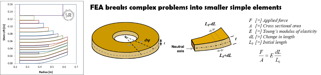
The circular geometry of shims directs forces applied at the shim edge into the smaller area of the pie slice tip. Focusing bending forces at the tip can push the shim center beyond the yield stress limit leaving the shim permanently bent.
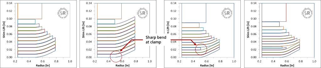
Shock absorbers use tapered shim stacks to supply more support at the shim center and increase the bend radius to avoid overstressing the shims. Split shim crossover configurations are used for the same reason.
Shim stack structure deflection
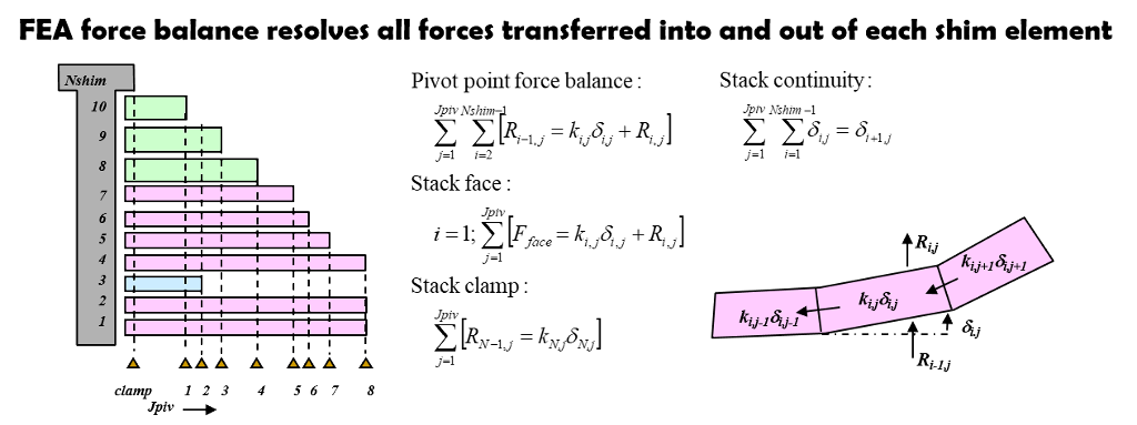
Forces applied at the shim stack edge are transferred through each FEA element, and tangentially out the sides of elements, into the shim center where the bending force is reacted by the shim stack clamp. Forces that cannot be reacted by bending are transferred out the top of the element into the shims above. A simple force in equals force out balance dictates the bending of each FEA element.
Solving the deflection of the shim stack structure requires the solution of thousands of simultaneous equations requiring all forces transferred into and out of each FEA element matches the forces transferred through all of the surrounding elements with the total force summing up to the force applied at the shim stack face.
Solution of thousands of simultaneous equations is nearly impossible by hand. Fortunately, computers are extremely efficient at solving FEA problems and GHz speeds makes solution of complex FEA shim stack problems possible in a matter of seconds.
FEA provides Shim ReStackor the capability to analyze complex shim stack structures with fine tuning adjustments to control the shim stack stiffness and shock absorber damping force far beyond the limits previously possible.
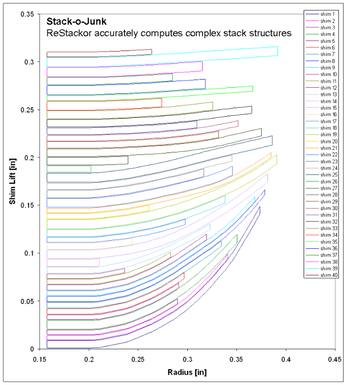
To demonstrate the capability of Shim ReStackor FEA calculations to resolve complex shim stack structures a random number generator was used to configure the shim stack below. The stack-o-junk has no practical application.
However, the configuration demonstrates the capability of Shim ReStackor to resolve complex shim stack structures with multiple crossover gaps and shim thickness variations creating a complex force transfer path through the shim stack to the stack clamp.
Fluid force on shim stack
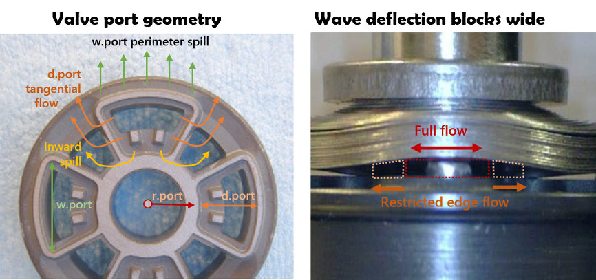
Shim ReStackor uses three parameters to specify the valve port geometry:
- r.port: Defines the inner radius where fluid pressure is applied to the shim stack face.
- d.port: Defines the valve port spoke length.
- w.port: Defines the valve port perimeter seat length.
The combination of d.port and w.port define the pressurized valve port pocket area applying fluid pressure to the shim stack face.
W.port also defines the pressurized perimeter length of the valve port and the tangential wave shaped deflection of the shim stack.
The fluid force acting on the shim stack face is the result of a highly interactive process between fluid dynamics and stack structure stiffness. Shim stack deflection sets the flow area and flow resistance of the valve port exit. The flow resistance sets the fluid pressure and forces acting on the shim stack face, which controls the shim stack deflection itself.
Shim stack flow area
D.port defines the radial spoke length metering tangential spill out the left and right sides of the valve port.
R.port defines the valve port inside radius and the location where fluid pressure is applied to the shim stack face. R.port also defines the inward spill area for shim stacks with a clamp diameter smaller than R.port. Inward spill is metered by the small wedge shaped area along the valve port spoke length.
Increases in shim stack clamp diameter produce a progressive increase in damping force up to the point where the stack clamp diameter overlaps r.port. Further increases in clamp diameter physically close off the inside diameter of the valve port resulting in larger increases in damping force. Dyno tuners refer to the increase as an example of the highly nonlinear behavior of shim stacks. In reality, the nonlinear behavior is caused by the simple geometric effect of closing off a section of the valve port.
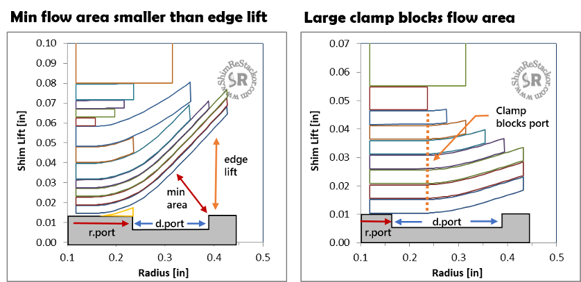
W.port defines the valve port perimeter seat length metering outward radial spill. As the shim stack deflects the curvature of the face shim forces the location of minimum flow area to move radially inward. Thorough FEA analysis of Shim ReStackor tracks the face shim bend profile and the location of minimum flow area which controls the shock absorber damping force.
Recognizing the minimum flow area does not occur at the outside edge provides an explanation of why shim stack edge lift and shim factors poorly correlate against damping force measured in dyno testing.
Fine tune damping force curves far beyond the limits previously possible
A simple listing of shim diameter and thickness specifies the shim stack configuration for Shim ReStackor calculations. Thorough FEA analyses computes the shim stack stiffness and bend profile of the stack face shim giving accurate and detailed accounting of the flow area produced.
Tuning shim stacks in software allows modifications to be rapidly evaluated and fine-tuned across the entire range of suspension velocities to perfect the shape and magnitude of the damping force curve and perfect performance of the suspension system far beyond the limits previously possible (more).