
Shock absorber fluid dynamics
Shim ReStackor models eleven tunable features of the shock absorber fluid circuits. Bleed systems control low speed damping. Flow restrictions control high speed damping and bottoming resistance.
Controlling the tuning of each feature gives control of the damping force curve shape and magnitude across the entire range of suspension velocities.
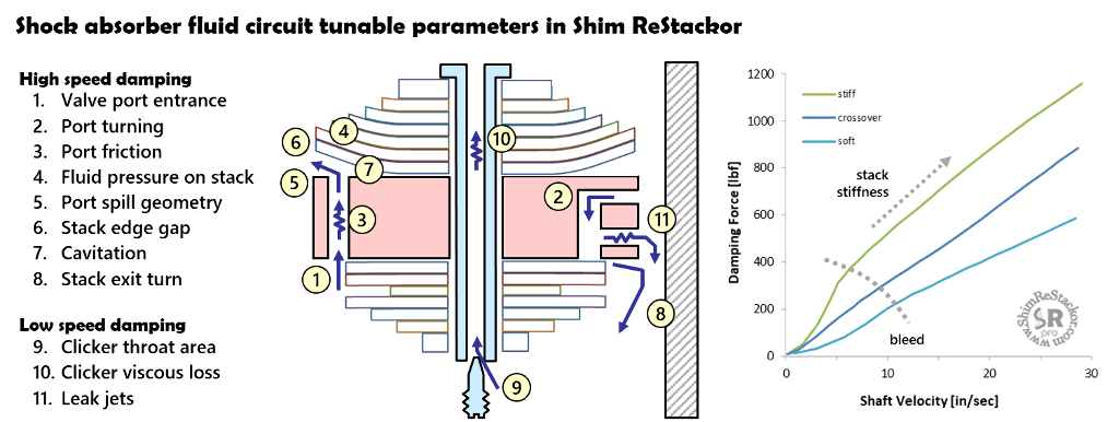
Shim ReStackor models eleven tunable features of shock absorber valves
Valve port entrance loss
Fluid enters the valve port through the annular slot between the valve deck and shim stack of the reverse flow circuit or holes drilled in the valve body side. Shim ReStackor models either inlet style with the critical parameter of entrance flow area.
Entrance losses can be minimized by increasing the port area or raising the reverse flow shim stack using delta shims to increase the deck height gap.
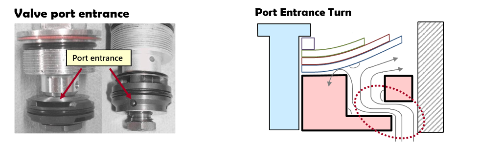
Port entrance turning losses increase damping force at high speed
Port turning loss
The 90 degree turn from the inlet into the valve port generates further flow losses. Shim ReStackor models the turn as a sharp 90 degree bend verified through dyno testing as an adequate estimate of the flow loss. The loss can be minimized by increasing the entrance port flow area to lower flow velocities and the resulting turning loss.
Evaluating potential modifications to the valve port geometry using Shim ReStackor allows the effect to be quantified and fine tuned before committing to irreversible modifications to the shock absorber valve hardware.
Viscous flow losses
Inputs of kinematic viscosity (cSt) at two temperatures and the fluid specific gravity define the suspension oil properties. Oil density, specified as specific gravity, directly impacts shock absorber damping force over the entire range of suspension velocity.
Inputs of oil viscosity at 40 centigrade (cSt.40c) and 100 centigrade (cSt.100c) coupled with the Andrade equation quantify temperature effects on oil viscosity (more).
The viscosity falloff with temperature determines viscous flow losses and Reynolds number effects on shock fade at high temperature allowing evaluation of the effect of brand-to-brand differences in oil properties on shock absorber damping performance.
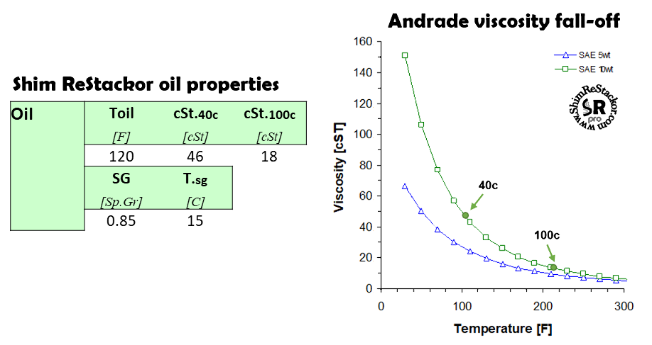
Oil properties define shock absorber damping force falloff and fade at high temperature
Valve port flow restriction
Compression pistons often include flow restrictions in the valve port throat to provide high speed bottoming resistance on hard hits. Port flow restrictions are modeled in Shim ReStackor using the d.thrt input.
Port flow restrictions can be tuned filling in the port with JB weld and re-drilling the port with a smaller or larger diameter.
Valve port throat restrictions increase damping force at high speed providing bottoming resistance
Shim stack flow area
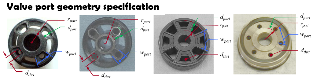
The flow area produced by shim stack deflection is the primary flow resistance through shock absorber valves. The input parameter w.port defines the dump area at the valve port perimeter. The d.port parameter defines the tangential flow dump area along the valve port side spokes.
As the shim stack deflects, curvature of the stack face shim causes the minimum flow area to move inward creating a throat with less flow area than the shim stack edge. Modifications to the shim stack structure change the shim bend radius, which in turn changes the location of the minimum throat area and the shock absorber damping force curve.
A central feature of Shim ReStackor FEA shim stack deflection calculations is a detailed accounting of the effects of shim stack structure on the shim bend profile, deflection of the face shim and the flow area produced (more).
The r.port valve geometry measurement defines the inside diameter of the valve port. Increasing the shim stack clamp diameter produce a progressive increase in damping force up to the point where the clamp diameter overlaps r.port. At that point, further increases in clamp diameter physically close off the inside diameter of the valve port creating larger changes in damping force.
Dyno tuners often refer to those type of effects as highly nonlinear shim stack behavior when in reality it is a simple geometric effect of the clamp shim closing off a section of the valve port. Shim ReStackor captures those effects and the shim stack deflection graphics makes those effects easy to understand.
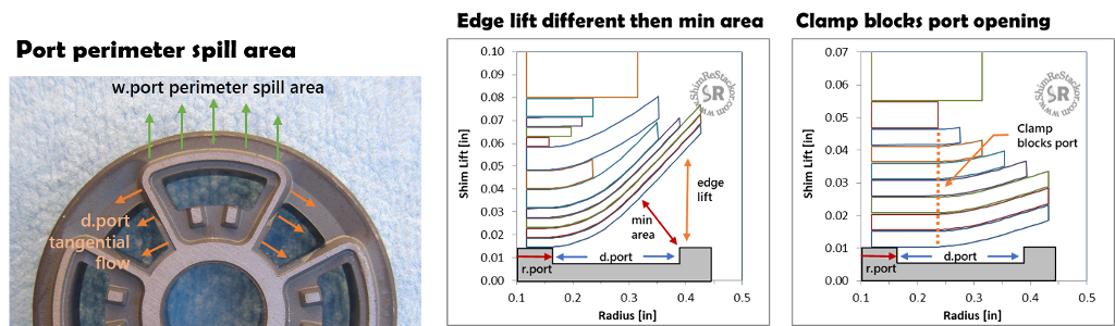
Valve port parameters w.port and d.port define the radial and tangential port spill area
Shim stack deflection
Shim stack deflection is controlled by the combination of fluid pressure on the shim stack face, fluid jet impingement force and the stiffness of the shim stack structure. The input parameters d.port and w.port define the pressurized pocket area applying fluid pressure to the shim stack face.
The d.thrt input defines the valve port throat flow restriction and the port jet momentum impacting the shim stack face. Those parameters coupled with the FEA analysis of the shim stack structure define deflection of the shim stack face shim and the flow area produced.
Cavitation oil foaming
Suspension oils contain 10% by volume dissolved gas measured as an Ostwald coefficient. When the shock gas reservoir is pressurized to 147 psi, gas will diffuse through the reservoir bladder, or around the o-ring seals of a piston reservoir, and saturate the oil with dissolved gas at 10% by volume after about four months. At that point the oil contains 100% gas by volume when the dissolved gas is expanded back to atmospheric pressure.
Dissolved gas makes suspension oils behave like a hot bottle of coca-cola. Keep the cap on and the fluid behaves like a liquid. Crack the cap and the drop in pressure allows the dissolved gas to boil out making the oil a foamy mess.
Preventing cavitation oil foaming requires tuning of shock absorber compression adjusters and fork base valves to backpressure the shock chambers and keep oil pressures well above the dissolved gas pressure. That keeps the gas from boiling out and foaming the oil.
Tuning of shock compression adjusters and fork base valves to backpressure the shock chambers for suppression of oil cavitation is known as pressure balancing the shock (more).
Stack exit turn
The fluid jet exiting the shim stack impinges on the shock body wall and turns 90 degrees. Backpressure from the turn increase pressures at the shim stack exit which in turn increases flow resistance.
Shim ReStackor inputs of the face shim diameter and piston diameter describe the tightness of the turn and the backpressure produced on the valve circuits.
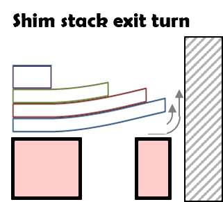
Flow turning at shim stack exit increases flow resistance
At low speed, below 10 in/sec, the shim stack is closed forcing all flow through the bleed circuits. The shock clicker bleed circuit is a simple needle valve. Shim ReStackor models seven factors controlling pressure losses through the clicker bleed circuit.
The discussion below steps through the clicker circuit in the rebound direction. In the compression stroke the flow is reversed. The fluid physics are the same but the flow losses are different due to the reverse flow and those effects are included in Shim ReStackor calculations.
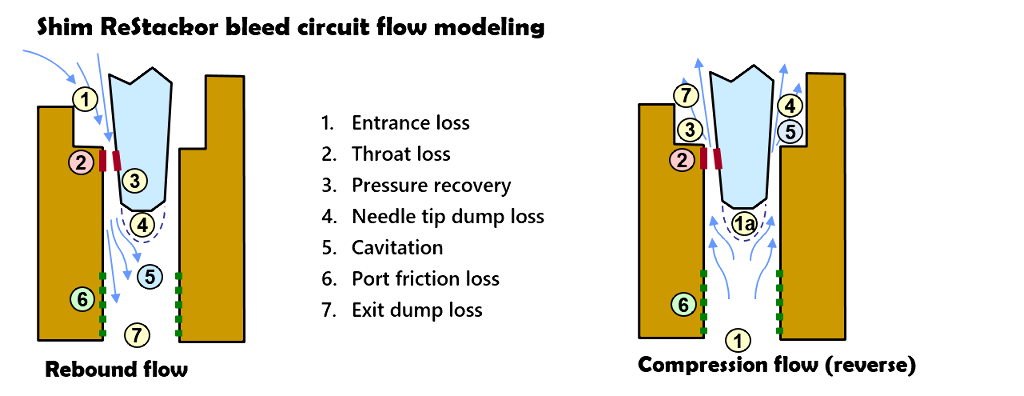
Shim ReStackor models seven flow features of the clicker bleed circuit
Entrance loss
Velocity gradients between converging streamlines at the clicker port entrance creates viscous shear loss. Higher oil viscosity increases the viscous loss.
Throat loss
The highest flow velocity occurs at the clicker needle throat minimum area specified by a simple function of clicker position (P. Skackauskas, Maintenance and Reliability 19(1):126-133, 2017). Flow resistance is a combination of fluid acceleration forces needed to force the fluid through the minimum area and skin friction viscous losses created by the high velocity. At the near closed clicker position the ratio of surface area to flow area becomes extremely high making viscous losses the dominate force.
Pressure recovery
Downstream of the throat, the expanding flow area of a tapered needle decelerates the flow. Pressure recovery through this region depends on the flow velocity, boundary layer thickness, friction loss and the needle taper angle. Stiff shim stacks forcing high velocities though the clicker circuits cause the flow to separate increasing the flow losses relative to a softer shim stack configuration.
Needle tip dump loss
At the needle tip the flow separates from the needle surface creating a dump loss. The magnitude of the pressure loss depends on the flow velocity at the needle tip, which in turn depends on the flow deceleration and pressure recovery through the tapered needle section.
Cavitation
Cavitation creates the psst, psst sound frequently heard rolling over small bumps. Stiff shim stacks, high flow velocities and large area expansions of blunt needles cause cavitation in the bleed circuits. Once cavitated, the cavitation bubbles crawl up the needle taper to the point that balances bleed circuit flow losses with the vapor pressure of dissolved gas in the oil, which varies with oil temperature. The fluid dynamic calculations of Shim ReStackor include those effects in computing the bleed circuit flow.
Port friction loss
Downstream of the needle tip the flow expands to the bleed port area. The expansion decelerates the flow and reduces viscous friction losses through the remainder of the bleed circuit. ReStackor uses Reynolds number based skin friction coefficients to determine viscous losses through this region under both laminar and turbulent flow conditions.
Exit dump loss
At the bleed port exit the flow spills into the downstream fluid reservoir. The sudden area expansion produces a second dump loss similar to the flow losses occurring at the needle tip.
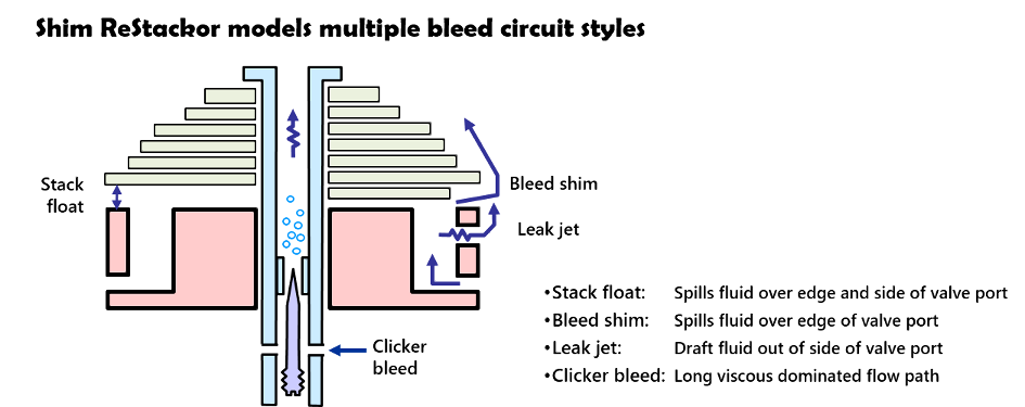
Leak jets
Leak jets are small holes drilled in the side of the valve port. At low speed, pressurized fluid escapes through the leak jet reducing low speed damping forces.
As speeds increase, high fluid velocities in the valve port are unable to negotiate the sharp 90 degree turn into the leak jet, which reduces the flow and the effectiveness of the leak jet at high speed.
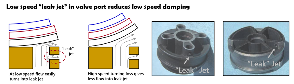
Shim ReStackor models single and multiple valve port leak jets
Three small jets are more efficient than one large jet. Adding a leak jet to a valve port increases the fluid flow through that port. Higher flow increases the pressure losses at the valve port entrance, which partially defeats the purpose of the leak jet.
Multiple smaller jets, distributed across the valve ports, produce a smaller flow increase into each port. Since flow losses increase with velocity squared, the increase in entrance flow loss is less when distributed across multiple ports.
That creates a situation where a single large leak jet on one port is less effective than multiple smaller leak jets distributed across all ports with the same total flow area.
In broad terms, a 1 mm2 bleed area through a leak jet, bleed shim, stack float or clicker circuit produce the same effect. In detail, the long flow path of clicker bleed circuits increase viscous flow losses reducing the bleed flow. Bleed shims or stack float draw fluid equally through all ports while a leak jet increases the flow through a single port creating higher flow losses reducing the effectiveness.
Those differences make the performance of each bleed circuit slightly different creating a situation where 1 mm2 of flow area through each type of bleed circuit gives slightly different performance (more).
Shim ReStackor handles the detailed flow physics for each type of bleed circuit. When tuning, bleed circuits are simply increased or decreased, or changed from a bleed shim to a leak jet or shim stack float and adjusted to get the desired effect. The calculations handle the detailed flow accounting so you can focus on tuning.
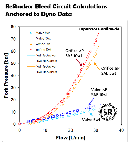
High speed flow loss verification
Super Cross OnLine has published a series of dyno tests using a hydraulic pump to force fluid through suspension valves and directly measure the flow resistance for a range of shim stack configurations and valve port geometries.
Using a hydraulic pump the tests can push fluid velocities far beyond the limits of conventional dyno testing to obtain true high speed performance data. Shim ReStackor fluid dynamic calculations closely match the Super Cross OnLine data.
Shock absorber fluid dynamics
Multiple fluid circuits control the damping performance of shock absorbers. Valve port geometry, shim stack configuration, oil density, viscosity, temperature, bleed systems and back pressure devices suppressing cavitation all play a role. However, accurate fluid dynamic analysis is not enough to define shock absorber performance.
Shock absorber performance also depends on the stiffness and deflection of the shim stack requiring FEA structural analysis to define the deflection and flow area at the shim stack face.
The combination of fluid dynamics and structural analysis creates a multi-physics problem. Solving the problem requires combining fluid dynamics, structural analysis and suspension response analysis tools into a single integrated package. Shim ReStackor integrates those multi-physics tools into a simple to use spreadsheet based analysis tool providing the capability to fine tune suspension setups far beyond the limits previously possible.

Fine tune suspension setups far beyond the limits previously possible