Suspension response
The physics of F=ma dictates suspension motion, bottoming velocities and suspension response. Spring-mass-damper theory applies that basic physics to define response of suspension systems for the ideal case of linear spring rates and linear shock damping (more).
However, actual suspension systems have nonlinear link ratios; nonlinear damping and nonlinear gas spring forces. Quantifying response of nonlinear systems requires stepping through the suspension stroke, a microsecond at a time, summing up all of the forces acting on the suspension to determine the resulting F= ma acceleration. With acceleration known, the change in suspension velocity and position can be computed and the calculations advanced to the next microsecond in time. Shim ReStackor calculations perform that numerical integration to define response of nonlinear suspension systems.
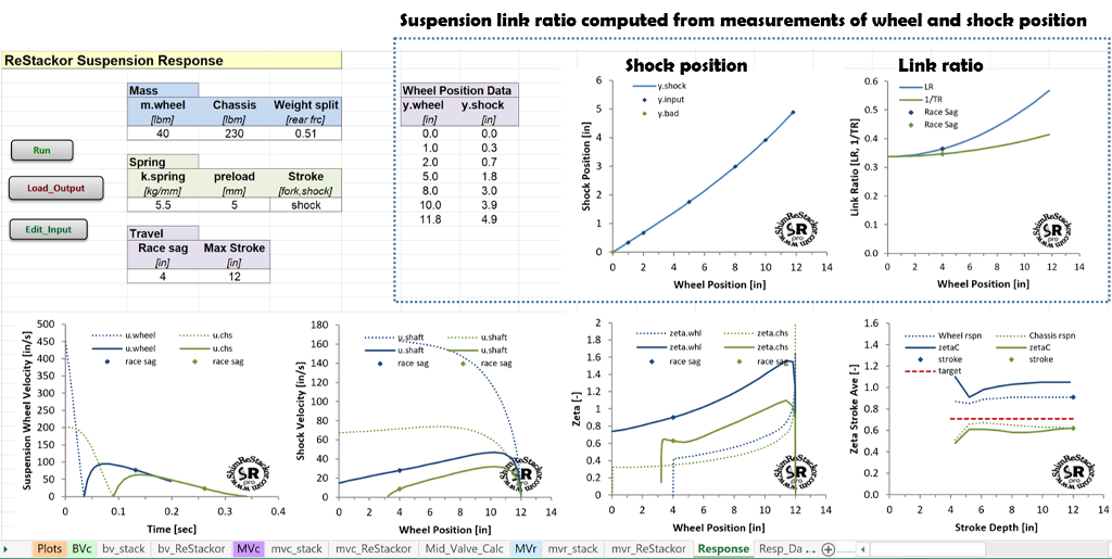
Suspension link ratio
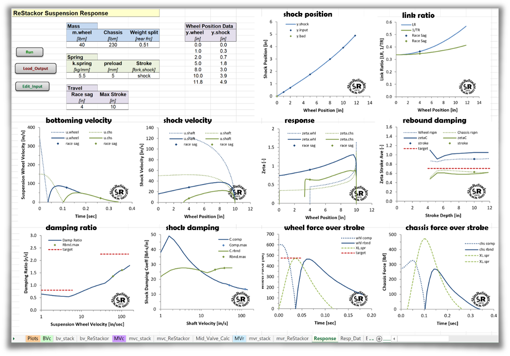
Shim ReStackor computes the suspension link ratio from inputs of measured wheel and shock shaft positions. The inputs of spring rate and preload define the spring force and inputs of fork oil level, ICS configuration and the shock gas reservoir pressure define the gas spring force allowing ReStackor to compute the changes in gas spring force through the stroke.
The damping force in compression and rebound are computed by Shim ReStackor from inputs of the shim stack configuration and valve port geometry. Seal drag and the change in seal drag with pressure is also computed by Shim ReStackor.
Suspension response calculations combined all of the above forces to determine the bump velocity that bottoms the suspension and the response time for rebound to return to race sag.
Suspension bottoming
There are two ways to bottom a suspension:
- Hit a bump hard enough for the wheel to blow through the compression stroke and hit bottom
- Land a jump hard enough for the chassis plus rider weight to crush through the compression stroke and tap bottom
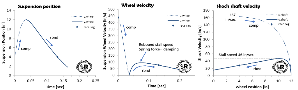
Wheel bottoming velocity
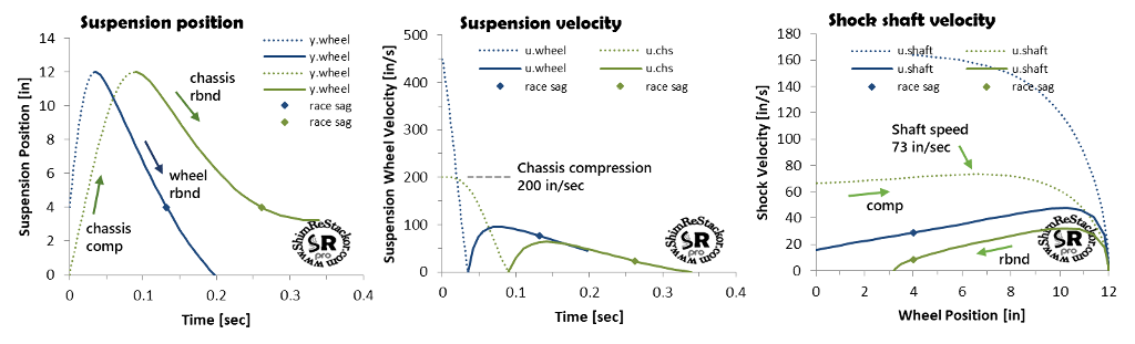
The “Max Stroke” input specifies the stroke depth evaluated. Internal calculations determine the bump velocity necessary for the wheel weight to blow through the compression stroke and hit the target “Max Stroke” depth. For the example below, a wheel bump velocity of 450 in/sec is required to push the suspension into a 12 inch stroke. On the bottoming stroke, the maximum shock shaft velocity is 167 in/sec set by the suspension link ratio. There is no point in tuning the shock beyond that shaft speed as the suspension is bottomed and at that point the bump rubber controls suspension motion, not the shock.
From the “Max Stroke” depth at 0.04 seconds, the calculations continue into the rebound stroke hitting the maximum rebound speed at 0.065 seconds. At the maximum rebound speed, the shock damping force matches the suspension spring force producing a suspension stall speed. As the suspension extends beyond that point, the drop in spring force slows the suspension velocity and the lower velocity reduces the rebound damping force producing progressively lower stall speeds as the suspension extends. The shock must also decelerate the wheel momentum, which is included in Shim ReStackor calculations.
Shim ReStackor calculations show the maximum rebound shock shaft velocity is 46 in/sec. There is no point in tuning the shock beyond that rebound speed, as the suspension cannot reach those velocities.
The suspension requires 0.13 seconds from bump impact to return to race sag. At 30 mph the bike travels 5.5 feet over that time which defines the bump spacing that packs rebound.
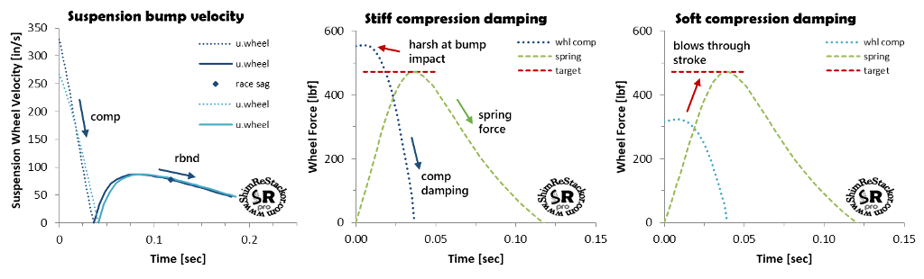
Force over stroke
Compression damping forces are highest at bump impact and drop off as the suspension slows through the stroke. Spring force, on the other hand, ramps up through the stroke reaching a maximum at bottoming. Target tuning sets the peak compression damping force to match the peak spring force. Matched peak force produces a nearly constant force through the stroke with compression damping dropping off as the spring force ramps up to keep the overall force approximately constant through the stroke. Constant force produces a consistent suspension “feel”.
Stiff compression damping produces a bump impact force that is higher than the peak spring force. That produces a bang at bump impact making the suspension harsh.
Soft compression damping produces a bump impact force less than the peak spring force allowing the stroke to “blow through” and get stiffer deeper in the stroke when the spring force ramps up.
To get “plush” the compression damping force at bump impact needs to match the peak spring force at stroke end.
Matched peak force produces a nearly constant force through the stroke with compression damping dropping off as the spring force ramps up keeping the overall force nearly constant. Constant force absorbs the maximum bump energy and minimizes the g-force transferred to the rider.
Setting compression damping to match the peak spring force is easy with Shim ReStackor. Response calculations plot the instantaneous spring and damping force through the stroke. Matching compression damping to the peak spring force simply requires hacking around on the compression shim stacks to line up the peak force. The matched force criteria should be applied at the stroke depth where the fork stroke hits the bottoming cones or bump rubber on a shock, typically 80% of max travel. Suspension “feel” beyond that point is controlled by the bottoming system, not the shock.
Beyond bottoming control, response calculations also quantify small bump compliance for tuning of crossover gaps to improve wheel traction (more).
Chassis bottoming velocity
The second way to bottom a suspension is land a jump hard enough for the bike plus rider weight to crush through the compression stroke and tap bottom. Chassis bottoming on a 12 inch suspension stroke is shown by the green curves in the example below. Chassis bottoming requires an impact velocity of 200 in/sec equivalent to a 4.3 foot jump free-fall. The maximum shock shaft velocity on the bottoming stroke is 73 in/sec. Changing the spring rate or damping changes the bottoming velocity (more).
Stroke velocities that bottom the chassis define the shocks low speed damping force range. Wheel bottoming defines the high speed range. Those velocities are specific to the spring rate and rider weight of the suspension setup. Knowing shaft velocities that control jump landings and the high speeds of wheel bottoming strokes allow the shocks damping force curve to be reshaped to correct specific suspension ills occurring at the different speeds of chassis and wheel motions (more).
Rebound tuning
Linked suspension systems increase spring force and damping as the suspension is driven deeper into the stroke (more). Small strokes around race sag produce little effect. Deeper strokes produce progressively larger effects driving the suspension into an over-damped condition. Defining response of nonlinear linked suspension systems requires definition of a stroke averaged suspension response coefficient.
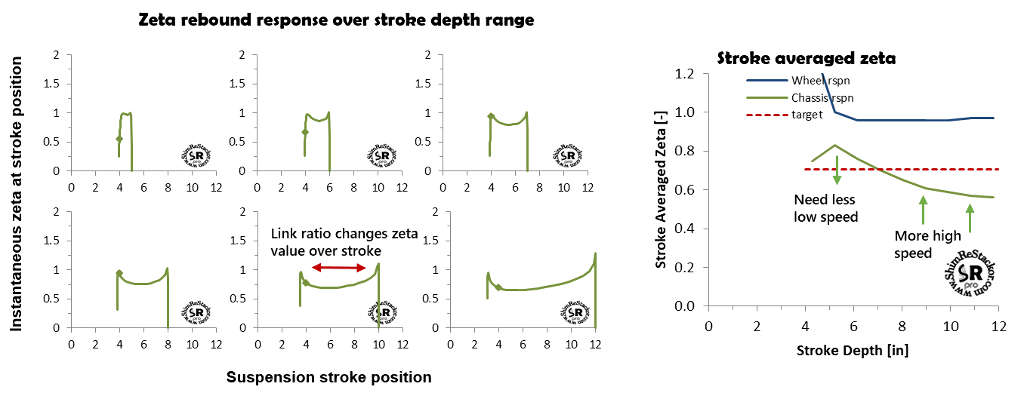
Shim ReStackor response calculations define the stroke averaged response coefficient as the ideal spring-mass-damper zeta value that matches the nonlinear system response time and final velocity on return to race sag. To determine those values Shim ReStackor computes the nonlinear system response starting with short strokes around race sag. At each stroke depth, the calculations determine the stroke averaged response coefficient that matches the nonlinear system response. The calcultions continue to progressively deeper strokes up to the maximum stroke depth specified by the link ratio input table.
The calculations determine the “Stroke Averaged Zeta” response coefficient and plot the results from race sag to the maximum stroke depth at suspension bottoming.
To produce a consistent suspension response, “feel” and behavior the value of “Zeta Stroke Ave” needs to be constant across the range of stroke depths.
The example below shows the stroke averaged zeta value falls off on deep strokes. To correct that behavior the suspension needs increased high speed rebound damping to keep the suspension for kicking on deep strokes. Short strokes around race sag produce zeta values greater than 0.7. Stiff rebound damping at low speed will cause the suspension to pack on small bumps. Fixing low speed requires retuning the shim stack crossover (more).
Suspension response tuning
The basic physics of F=ma dictates suspension motions. Shim ReStackor applies that basic physics to compute the effect of spring rate, link ratio, gas force, bike weight, rider weight and damping on suspension response and performance. Response calculations quantify bump velocities that bottom the wheels and jump landings that bottom the chassis.
Detailed outputs quantify spring force and damping over the stroke. Those details provide specific tuning targets needed to create a balanced and well damped “Baseline suspension setup” (more).